High-speed moving parallel mechanical arm with six degrees of freedom

A high-speed motion and degree of freedom technology, applied in the field of robotics, can solve problems such as increasing the mass and inertia of moving parts, making it difficult to achieve high-speed motion, and affecting the dynamic performance of the mechanism, so as to achieve overall structure symmetry, satisfy complex pick-and-place operations, and light weight Effect

Inactive Publication Date: 2013-01-02
天津大学中原先进技术研究院(开封)有限公司
View PDF7 Cites 7 Cited by
  • Summary
  • Abstract
  • Description
  • Claims
  • Application Information

AI Technical Summary

Problems solved by technology

The limitation of the above-mentioned mechanism is that the driving end of the three-degree-of-freedom wrist is fixed between the two remote frame rods, which increases the mass and inertia of the moving parts of the mechanism, affects the dynamic performance of the above-mentioned mechanism, and makes it difficult for the mechanism to achieve high-speed movement

Method used


Image

  • High-speed moving parallel mechanical arm with six degrees of freedom
  • High-speed moving parallel mechanical arm with six degrees of freedom
  • High-speed moving parallel mechanical arm with six degrees of freedom

Examples


Embodiment approach 1

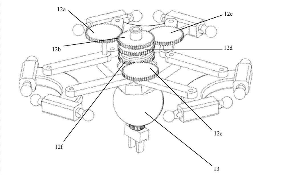
[0025] Each set of gear mechanisms includes a large gear and a small gear, wherein the large gear is fixedly connected to a connecting rod in a set of connecting rods, the rotation axis of the large gear coincides with the rotation axis of the connecting rod on the center plate, and the small gear and One input shaft of the three-degree-of-freedom wrist is fixedly connected, and the rotation axis of the pinion coincides with the axis of one input shaft. Such as image 3 As shown, the three large gears 12a, 12c, 12e are fixedly connected to one of the connecting rods 11a, 11c, 11e in the three sets of connecting rods respectively, and the rotation axis of the large gear and the rotation axis of the fixed connecting rod on the center plate Coincident; the three pinions 12b, 12d, 12f are fixedly connected to an input shaft of the three-degree-of-freedom wrist 13 respectively, and the rotation axis of the pinion coincides with the axis of the fixed input shaft. Three large gears ...

Embodiment approach 2

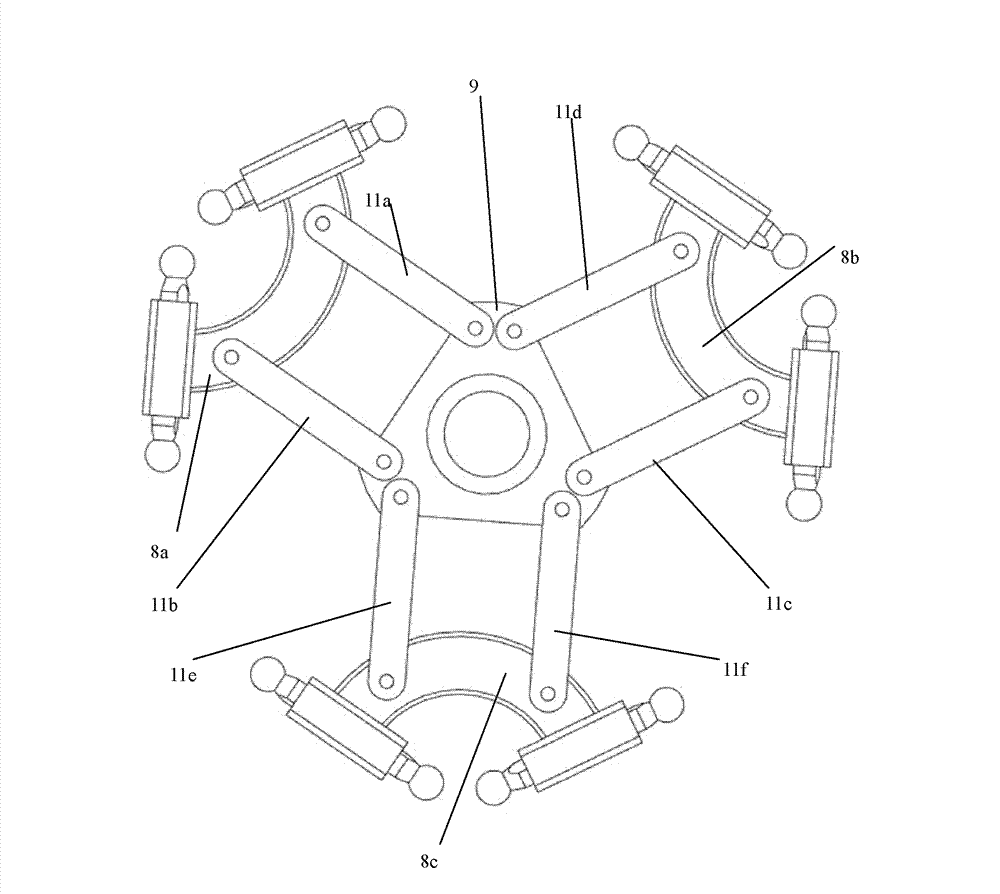
[0027] The gear mechanism includes a large gear and a small gear, wherein the large gear is affixed to the club base, the pinion is affixed to an input shaft of the three-degree-of-freedom wrist, and the rotation axis of the pinion is connected to one of the three-degree-of-freedom wrists. The axis of the input shaft coincides, and the common vertical segment of the rotation axis of the pinion and the rotation axis of the bull gear is parallel and equal in length to the connecting rod in the parallelogram structure. Such as Figure 4As shown, the three large gears 12a, 12c, 12e are fixedly connected to the three club mounts 8a, 8b, 8c respectively, and the three small gears 12b, 12d, 12f are respectively fixedly connected to an input shaft of the three-degree-of-freedom wrist 13, And the rotation axis of the pinion coincides with the axis of the input shaft of the fixed three-degree-of-freedom wrist 13 . Three bull gears 12a, 12c, 12e and three pinion gears 12b, 12d, 12f form...


PUM


Abstract

The invention discloses a high-speed moving parallel mechanical arm with six degrees of freedom. The mechanical arm comprises a fixed mount, a movable platform, a three-degree-of-freedom wrist, and six moving branch chains which are arranged between the fixed mount and the movable platform and are of a same structure, wherein the movable platform comprises a central plate, three ball arm seats and three groups of connecting rods; each connecting rod group is composed of two parallel connecting rods with the same length; the ball arm seats are rotationally connected with the central plate through one group of connecting rods to form a group of parallelogram structures; the movable platform is provided with three groups of parallelogram structures; the three-degree-of-freedom wrist is fixedly connected with the central plate; three input axes of the three-degree-of-freedom wrist are arranged coaxially or in parallel and are parallel to a rotating axis on the central plate; three groups of gear mechanisms are arranged in the three groups of parallelogram structures; and the rotation of the connecting rods in each group of parallelogram structures relative to the central plate or the parallel movement of the ball arm seats relative to the central plate is converted into the controllable movement of the three-degree-of-freedom wrist.

Description

technical field [0001] The invention relates to a robot, in particular to a parallel mechanism with six degrees of freedom in space that can realize high-speed movement. Background technique [0002] Patent document US20110097184A1 discloses a parallel mechanism capable of three-dimensional translation and three-dimensional rotation, including a fixed frame, a moving platform, a three-degree-of-freedom wrist, and three branch chains with the same structure symmetrically arranged between the fixed frame and the moving platform; A driving end is affixed to the fixed frame; a lower connecting shaft is affixed to the moving platform; each branch chain includes a near frame rod and two parallel far frame rods, a driving end and a connecting shaft, and the near frame rod One end is affixed to the upper driving end of the fixed frame, and the other end is affixed to the upper connecting shaft; one end of the two parallel remote frame rods is respectively ball-hinged to the two ends...

Claims


Application Information

Patent Timeline
IPC IPC(8): B25J9/08B25J17/00
Inventor 王攀峰赵学满
Owner 天津大学中原先进技术研究院(开封)有限公司
Why Eureka
Try Eureka