Ducted lift-fan flow deflectors and transmission mechanism thereof

A technology of lift fan and transmission mechanism, which is applied to aircraft parts, aircraft control, transportation and packaging, etc., and can solve problems such as single working mode

Inactive Publication Date: 2013-01-02
NORTHWESTERN POLYTECHNICAL UNIV
View PDF5 Cites 1 Cited by
  • Summary
  • Abstract
  • Description
  • Claims
  • Application Information

AI Technical Summary

Problems solved by technology

The existing deflector drive usually controls the same direction and synchronous deflection of multiple deflectors through a connecting rod, and the working mode is relatively single

Method used


Image

  • Ducted lift-fan flow deflectors and transmission mechanism thereof
  • Ducted lift-fan flow deflectors and transmission mechanism thereof
  • Ducted lift-fan flow deflectors and transmission mechanism thereof

Examples


Embodiment Construction

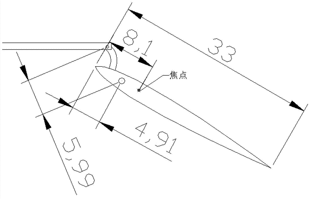
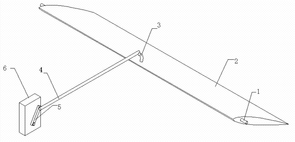
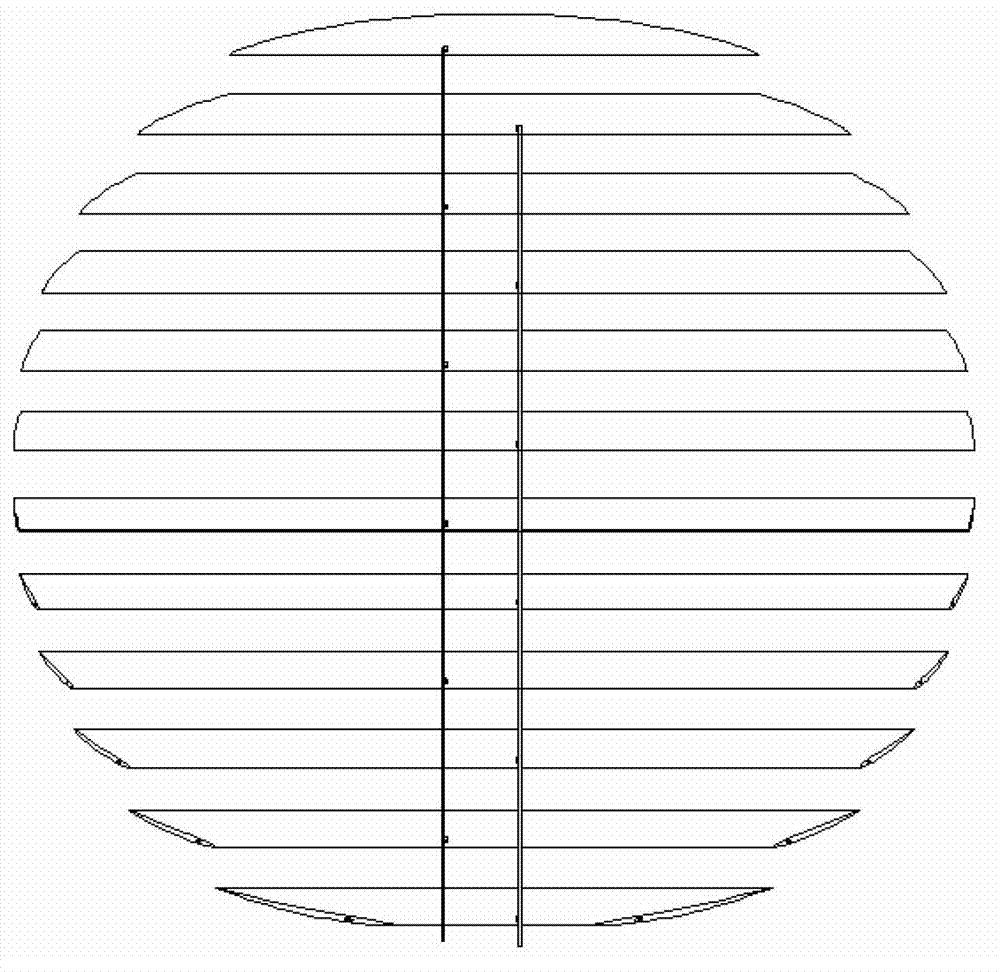
[0017] The invention includes steering gear, deflectors and transmission connecting rods. Several deflectors are arranged in parallel, and are installed in the duct through the rotating shafts at both ends of the deflectors. Adjacent to each other, the output shafts of the two steering gears are respectively connected to different transmission linkages through rotating rods, and one transmission linkage is hinged to a set of curved rods fixed on the deflectors to drive the angular deflection of the deflectors. Different steering gears are controlled to adjust the deflection of each set of deflectors, and through the cooperation of the two sets of deflectors, different direction control of the ducted airflow is realized.

[0018] When the angle between the guide vanes of the two groups is 0°, the guide vanes are completely closed in the duct.

[0019] The deflector airfoil is a low-speed symmetrical airfoil of the NACA series.

[0020] Each deflector is connected to the duct w...


PUM


Abstract

The invention discloses ducted lift-fan flow deflectors and a transmission mechanism thereof. According to the invention, a plurality of flow deflectors are arranged in parallel, and are arranged in a ducted through rotation shafts provided on two ends of each of the flow deflectors. The flow deflectors are divided into two sets, and flow deflectors in each set are not pairwisely adjacent. Output shafts of two servos are respectively connected with different transmission links through rotation rods. One transmission link is hinged with a bent bar fixedly connected to a set of flow deflectors. With the structure, flow deflector angle deflection can be driven. With the flow deflectors and the transmission mechanism provided by the invention, air flow direction can be changed, and air flow volume can be controlled. The structure is simple, safe, and reliable. With the flow deflectors and the transmission mechanism, aircraft structural requirements can be satisfied, good aerodynamic efficiency is provided, and multi-dimensional deflection effect is realized.

Description

technical field [0001] The invention relates to a mechanism design for controlling the air flow at the outlet of a ducted lift fan, specifically including a deflector and a transmission mechanism for controlling the deflection and combined movement of the deflector. Background technique [0002] The ducted fan is an axial fluid propulsion device, so the airflow through the duct can only flow in the axial direction, especially when the axial direction is vertical. In order to effectively utilize the power of the ducted fan, a guide vane suitable for the outlet is added in the duct, and the direction of the outlet airflow is controlled by deflection of the guide vane. [0003] The deflector adopts the airfoil as the basic shape, and when the lift fan in the duct provides low-speed airflow, it is suitable to adopt the low-speed airfoil. When the deflector is near a certain medium angle of attack, the airflow on the airfoil is the best, showing an attached flow with a small sep...

Claims


Application Information

Patent Timeline
Patent Type & Authority Applications(China)
IPC IPC(8): B64C9/00
Inventor 张炜张引妮申懿郭大鹏蒋汉杰
Owner NORTHWESTERN POLYTECHNICAL UNIV
Why Eureka
Try Eureka