Continuous and changeable valve lift control mechanism

A valve lift and control mechanism technology, applied to mechanical equipment, engine components, machines/engines, etc., can solve problems such as inability to change valve lift, unfavorable engine layout, and increased engine height

Inactive Publication Date: 2013-01-02
GREAT WALL MOTOR CO LTD
View PDF4 Cites 8 Cited by
  • Summary
  • Abstract
  • Description
  • Claims
  • Application Information

AI Technical Summary

Problems solved by technology

[0003] In order to solve the above problems, the variable valve timing technology (VVT) currently used in automobile engines is to adjust the phase of the intake and exhaust valves according to different engine operating conditions, that is, to control the opening and closing timing of the intake and exhaust valves, but the VVT ​​technology It can only adjust the opening and closing time of the valve, but canno...

Method used


Image

  • Continuous and changeable valve lift control mechanism
  • Continuous and changeable valve lift control mechanism
  • Continuous and changeable valve lift control mechanism

Examples


Embodiment Construction

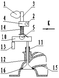
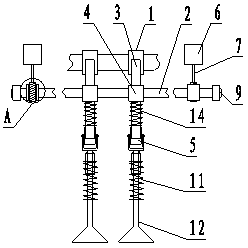
[0025] Referring to Fig. 1 and Fig. 2, the present invention includes a transmission assembly and a valve assembly, and the transmission assembly includes a cam 1, a rocker shaft 2, a rocker 3, a rocker support block 4, a rocker roller 5, a rocker 10 and a hydraulic lifter The column 13 is special in that: the rocker shaft 2 can move up and down driven by the height adjustment motor 6, and the height adjustment motor 6 is fixedly installed on the engine cylinder head 15.

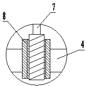
[0026] See Figure 1, figure 2 , image 3 , the rocker shaft 2 of the present invention is connected with the height adjustment motor 6 through a screw nut transmission mechanism, the screw nut transmission mechanism is composed of a height adjustment screw 7 and a height adjustment nut 8, and the height adjustment screw 7 is fixedly mounted on the height adjustment motor 6 on the output shaft, the height adjustment nut 8 is fixed on the rocker shaft 2, and the rocker shaft slider 9 fitted with the slideway...


PUM


Abstract

Disclosed is a continuous and changeable valve lift control mechanism. The control mechanism is used for solving the control problem of valve lift matched with different working conditions of an engine. The control mechanism comprises a transmission component and a valve component. The transmission component comprises a cam, a rocker, a rocker supporting block, a rocker shaft, a rocker arm roller, a rocker arm and a hydraulic tappet. The control mechanism is characterized in that the rocker shaft can move up and down driven by a height adjusting motor which is fixedly mounted on an engine cylinder cover. The continuous and changeable valve lift control mechanism matched with a variable valve timing (VVT) system can be matched with the engine working conditions to adjust the valve opening lasting period and opening and closing moments, so that the gas feeding efficiency of the engine in all working conditions is the best, and the control mechanism is helpful for improving dynamic and economic properties and the discharge of the engine.

Description

technical field [0001] The invention relates to a control technology of an engine valve mechanism, in particular to a continuously variable valve lift mechanism of an automobile engine, belonging to the technical field of combustion engines. Background technique [0002] Improving the charging efficiency of the engine is an effective way to improve the economy and power of the vehicle. Since the optimal intake air volume required by the automobile engine is different under different working conditions, and the cam profile that controls the valve action is fixed, the traditional engine The gas distribution mechanism can only meet the optimal gas distribution requirements of some working conditions. [0003] In order to solve the above problems, the variable valve timing technology (VVT) currently used in automobile engines is to adjust the phase of the intake and exhaust valves according to different engine operating conditions, that is, to control the opening and closing tim...

Claims


Application Information

Patent Timeline
IPC IPC(8): F01L13/00
Inventor 崔亚彬孙磊魏娜
Owner GREAT WALL MOTOR CO LTD
Why Eureka
Try Eureka