Rotating structure of lamp holder of track lamp

A technology of rotating structure and track lights, applied in the field of track lights, can solve the problems of uneven contact surface, damage to the overall appearance, sticking, etc., and achieve the effect of simple overall structure, strong manufacturability, and easy assembly.

Active Publication Date: 2015-05-20
SELF ELECTRONICS CO LTD
View PDF4 Cites 2 Cited by
  • Summary
  • Abstract
  • Description
  • Claims
  • Application Information

AI Technical Summary

Problems solved by technology

The structure is simple, suitable for lamps with riveting space, but the rotation torque is not easy to control, the torque consistency of the same batch of products is poor, and it is easy to wear during the rotation process, and the lamp head cannot be fixed after wear.
[0004] Although the lamp head rotation adjustment structures of the above several track lights are low in cost and easy to assemble, they have the following disadvantages: 1. During the adjustment process, the pre-tightening screws are easy to loosen, and they need to be pre-tightened again during use, resulting in inconvenient use; 2. During the adjustment process, the rotation of the lamp head is relatively stiff, and there will be stagnation, and it is easy to fail after repeated adjustments; 3. The contact surface is uneven, and it is easy to wear after rotation and friction, resulting in damage to the appearance of the lamp; 4. The rotating structure is exposed, which not only damages the The overall appearance, and the rigidity of the connection is poor, easy to shake

Method used


Image

  • Rotating structure of lamp holder of track lamp
  • Rotating structure of lamp holder of track lamp
  • Rotating structure of lamp holder of track lamp

Examples


Embodiment Construction

[0025] The present invention will be further described in detail below in conjunction with the accompanying drawings and embodiments.

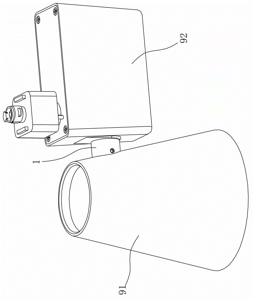
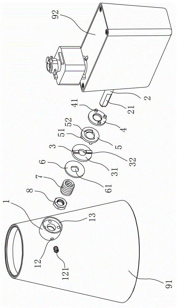
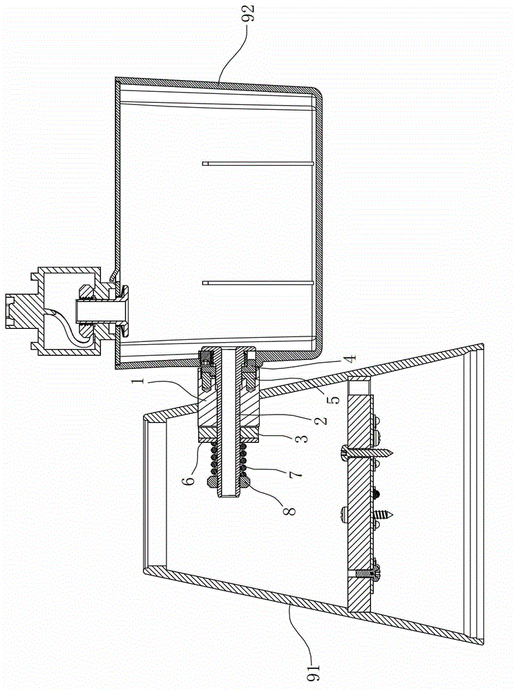
[0026] Such as Figure 1 to Figure 7 As shown, this embodiment is a rotating structure of the lamp head 91 of a track light, and the rotating structure of the lamp head 91 includes a shaft sleeve 1, a connecting shaft 2, a first stop disc 3, a second stop disc 4, and a limiting device 5 , Stop washer 6, elastic member 7 and lock nut 8.

[0027] Wherein, the lamp cap 91 of the track light has a shaft hole on the side wall, and a shaft sleeve 1 is fixedly arranged in the shaft hole. There is no relative rotation between the shaft sleeve 1 and the lamp cap 91, and the two can be fixed by welding or threaded connection; One end of the shaft 2 is inserted into the shaft sleeve 1 and is rotatably matched with the shaft sleeve 1. The other end of the connecting shaft 2 is fixedly connected to the bracket 92 (or power module) of the track light. The ...


PUM


Abstract

A rotating structure of a lamp holder of a track lamp is characterized by comprising a shaft sleeve, a connecting shaft, a first stopping disc, a stopping gasket and a locking nut. The shaft sleeve is fixedly and penetratingly arranged on a side wall of the lamp holder; one end of the connecting shaft is rotatably inserted in the shaft sleeve, and the other end of the connecting shaft is fixedly connected onto a support of the track lamp; the first stopping disc is fixedly connected onto a first opening end of the shaft sleeve extending into the lamp holder; the stopping gasket is sleeved at one end of the connecting shaft and is fixedly connected with the connecting shaft, and one end of the stopping gasket is in rotatable contact with the first stopping disc; and the locking nut is sleeved at one end of the connecting shaft and is abutted to the other end of the stopping gasket. Compared with the prior art, the rotating structure is good in concealment, and the integral appearance of the lamp cannot be destroyed; the lamp holder can rotate continuously and smoothly, torsion is consistent, and the problem of jamming is avoided; the lamp holder is in close contact with the support, and wearing and loosening are avoided after the lamp holder rotates by multiple times; and the integral rotating structure is simple and is high in manufacturability and easy to assemble.

Description

technical field [0001] The invention relates to a track light, in particular to a lamp cap rotation structure of the track light. Background technique [0002] Track light is a new type of lamp designed for commercial lighting or commodity display. Its lamp head adopts an adjustable structure, which can facilitate the adjustment of the light angle. [0003] In the prior art, the adjustment structure of the lamp head of the track light usually has the following types: 1. The lamp body and the bracket are pre-tightened directly by screws. When this structure is adopted, there will be direct or indirect friction between the lamp body and the bracket, which will not only damage the exterior paint surface to a certain extent, but also be prone to loosening, and it needs to be pre-tightened again after adjustment. 2. Tooth-shaped limit structure, that is, a pair of tooth surfaces are pre-tightened by screws, and the meshing of the tooth surfaces forms a certain torque to position...

Claims


Application Information

Patent Timeline
Patent Type & Authority Patents(China)
IPC IPC(8): F21V21/30
Inventor 李伟波林万炯
Owner SELF ELECTRONICS CO LTD
Why Eureka
Try Eureka