Material falling trajectory measurement method for blast furnace
A blast furnace and blanking technology, applied in the field of measurement, can solve problems such as time-consuming, poor accuracy, inconsistent drawing results, etc.
- Summary
- Abstract
- Description
- Claims
- Application Information
AI Technical Summary
Problems solved by technology
Method used
Image

Examples
Embodiment Construction
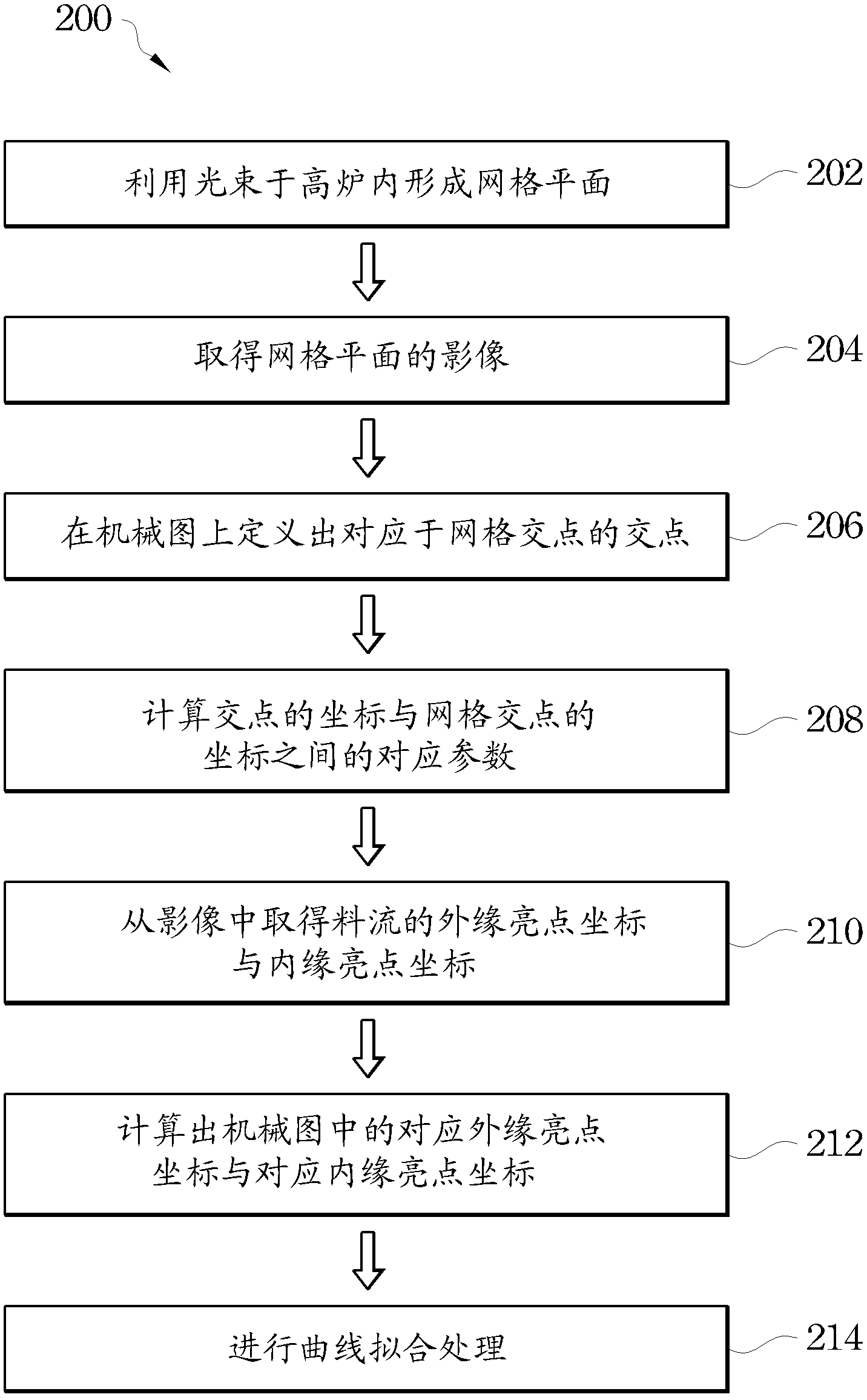
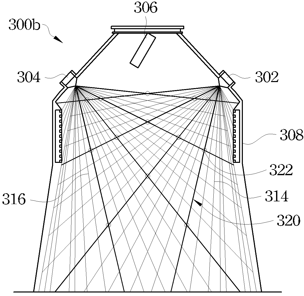
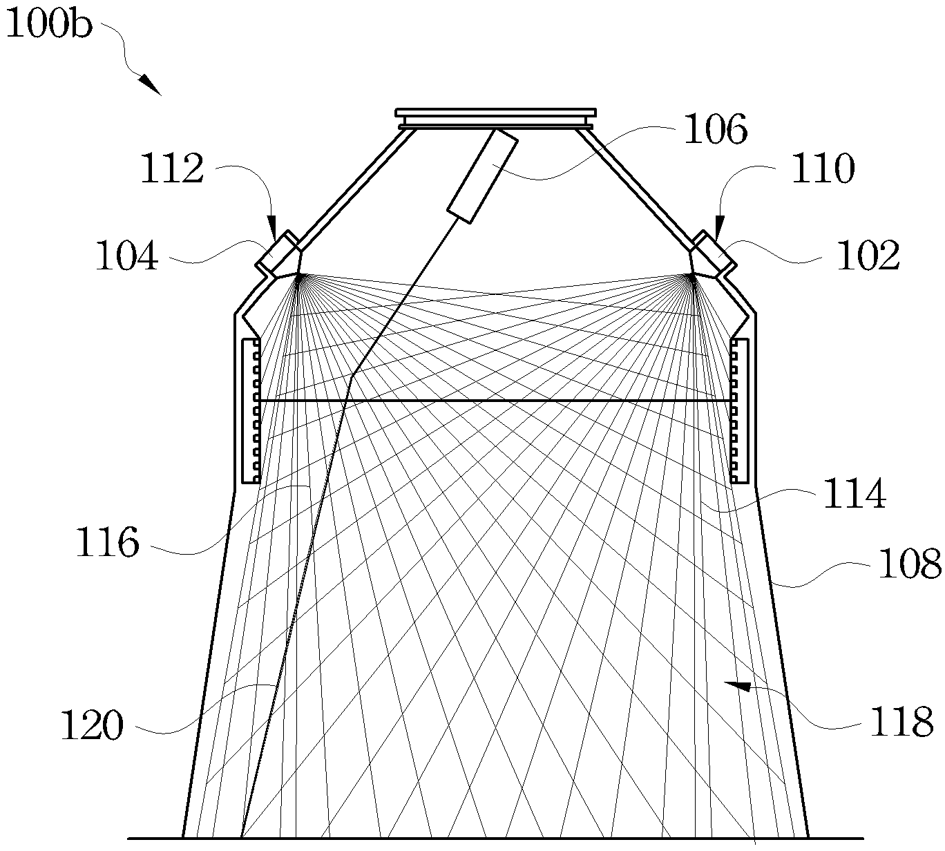
[0029] Please refer to Fig. 2, Fig. 3A and Fig. 3B together, which are respectively a flow chart showing a method for measuring the blanking trajectory of a blast furnace according to an embodiment of the present invention, and a method according to an embodiment of the present invention. A grid image within a blast furnace, and a blast furnace mechanical diagram corresponding to the blast furnace grid image of FIG. 3A. In this embodiment, when performing the method 200 for measuring the blanking trajectory of a blast furnace, as described in step 202, at least two strong light sources 302 and 304 are used to form several light beams 314 and 316 in the blast furnace 308, respectively. , as shown in Figure 3A and Figure 3B. These light beams 314 and 316 intersect to define a grid plane 320 within the blast furnace 308 . In an exemplary embodiment, the intense light sources 302 and 304 may be, for example, laser emitters.
[0030] Next, as described in step 204 of the measurem...
PUM
 Abstract
Description
Claims
Application Information
 - Generate Ideas
- Intellectual Property
- Life Sciences
- Materials
- Tech Scout
- Unparalleled Data Quality
- Higher Quality Content
- 60% Fewer Hallucinations
Browse by: Latest US Patents, China's latest patents, Technical Efficacy Thesaurus, Application Domain, Technology Topic, Popular Technical Reports.
© 2025 PatSnap. All rights reserved.Legal|Privacy policy|Modern Slavery Act Transparency Statement|Sitemap|About US| Contact US: help@patsnap.com