
Multimode optical fiber

A multi-mode optical fiber and core technology, applied in clad optical fiber, multi-layer core/clad optical fiber, optics, etc., can solve the problems of small diameter, increased manufacturing cost, width deposition, etc.

Active Publication Date: 2013-01-02
DRAKA COMTEQ BV
View PDF11 Cites 13 Cited by
  • Summary
  • Abstract
  • Description
  • Claims
  • Application Information

AI Technical Summary

Problems solved by technology

Constraints imposed by determining the location of the substrate tube typically result in a small diameter core rod, thereby increasing manufacturing costs
[0026] Thus, there is a need for a multimode fiber that includes a depressed cladding that limits the impact of leaky modes on other fiber properties (e.g., bandwidth, core size, and / or numerical aperture), but Possibly deposited into silica-based tubes at reduced width

Method used


Image

  • Multimode optical fiber
  • Multimode optical fiber
  • Multimode optical fiber

Examples


Embodiment Construction

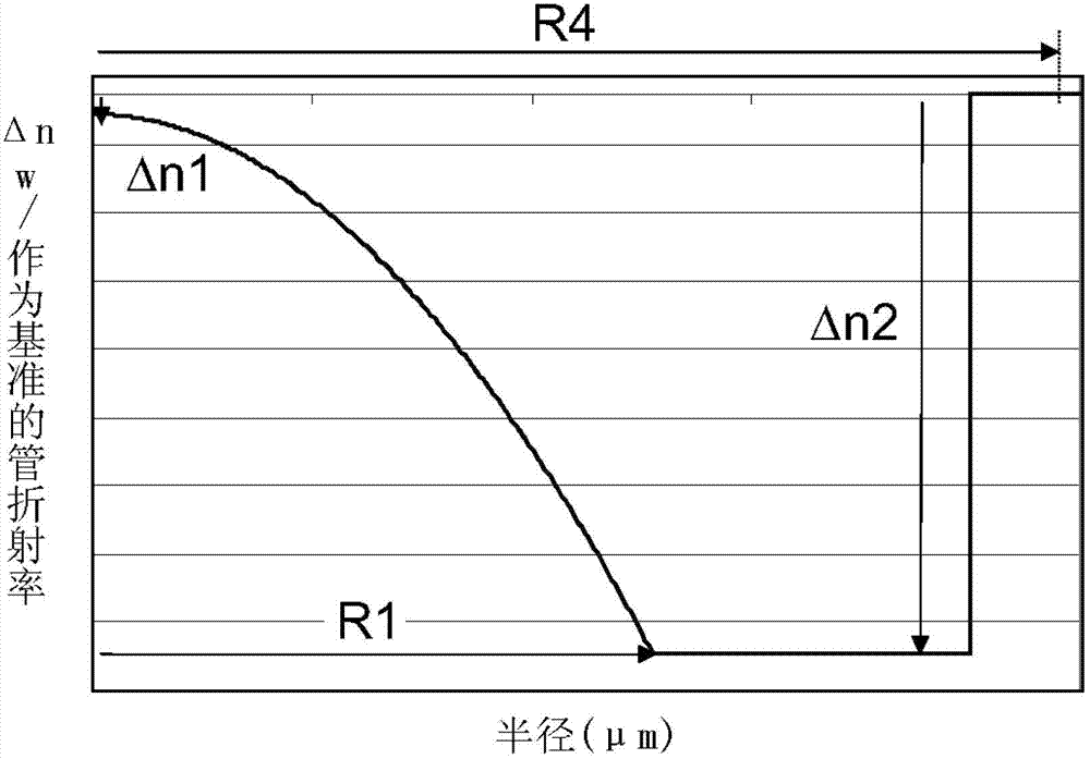
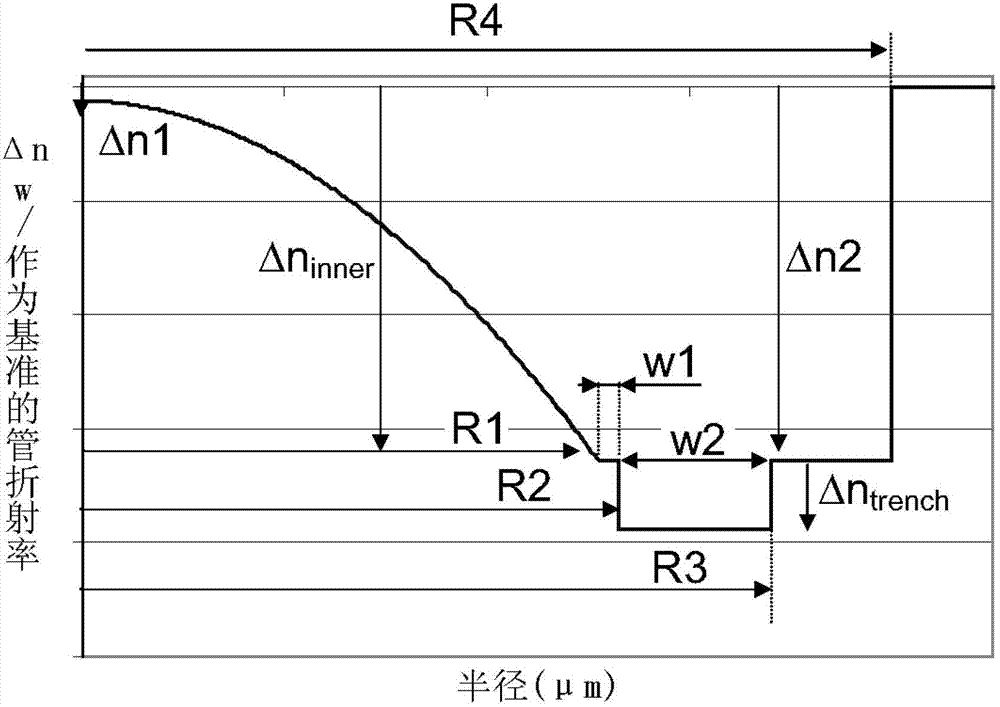
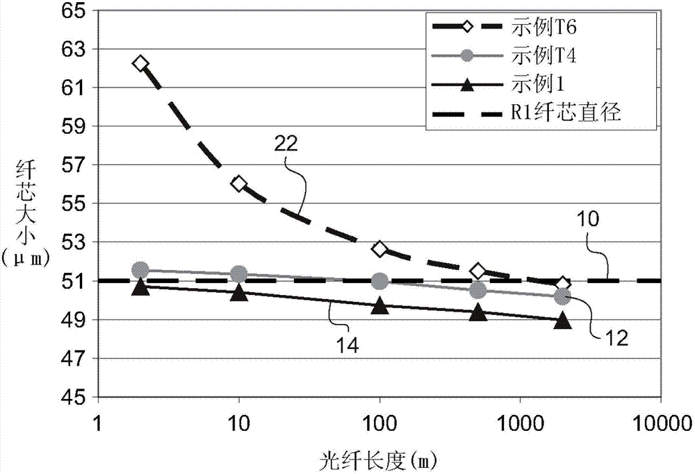
[0053] The present invention relates to concave graded-index multimode optical fibers comprising a depressed cladding that limits the contribution of leaky modes to other fiber characteristics (e.g., bandwidth, core size, and / or numerical aperture) influences.

[0054] There is increasing interest in the use of optical fibers in nuclear power plants and other radiation-rich environments such as particle acceleration laboratories and satellites. For example, optical fibers can be used in optical data communication links, distributed sensors, plasma diagnostics, and instrumentation systems. In these applications, optical fibers typically transmit signals through noisy electromagnetic environments, high gamma ray doses and / or dose rates, and high neutron fluxes.

[0055] Signals transmitted via optical fibers typically suffer from accumulated optical loss (ie, attenuation) over the distance traveled. These transmission losses increase substantially when the fiber is exposed to ...


PUM


Abstract

It is proposed a multimode optical fiber including a central core, an inner depressed cladding, a depressed trench, an outer depressed cladding, and an outer cladding. The central core has an alpha-index profile. The depressed claddings limit the impact of leaky modes on optical-fiber performance characteristics (e.g., bandwidth, core size, and / or numerical aperture).

Description

technical field [0001] The present invention relates to the field of optical fiber transmission, and more particularly, to a groove-assisted concave graded-index multimode optical fiber. Background technique [0002] Traditionally, an optical fiber (ie, a glass fiber typically surrounded by one or more cladding layers) includes an optical fiber core that transmits and / or amplifies optical signals and an optical cladding that confines the optical signals within the core. Therefore, the refractive index n of the core c Usually greater than the refractive index n of the optical cladding g (ie, n c >n g ). [0003] For optical fibers, the refractive index profile is usually classified according to the graphical appearance of the function relating the refractive index to the fiber radius. Traditionally, the distance r from the center of the fiber is shown on the x-axis, and the relationship between the refractive index (at radius r) and the refractive index of the fiber's...

Claims


Application Information

Patent Timeline
Patent Type & Authority Applications(China)
IPC IPC(8): G02B6/036G02B6/028
CPCG02B6/0365G02B6/0288G02B6/03683G02B6/03605
Inventor M・比戈-阿斯楚克D・莫林P・斯拉德
Owner DRAKA COMTEQ BV
Learn More