Method and device for scanning transformation coefficients
A technology of transform coefficient and scanning method, applied in the field of video coding and decoding, can solve the problem of low coding efficiency and achieve the effect of improving coding efficiency
- Summary
- Abstract
- Description
- Claims
- Application Information
AI Technical Summary
Problems solved by technology
Method used
Image


Examples
no. 1 example
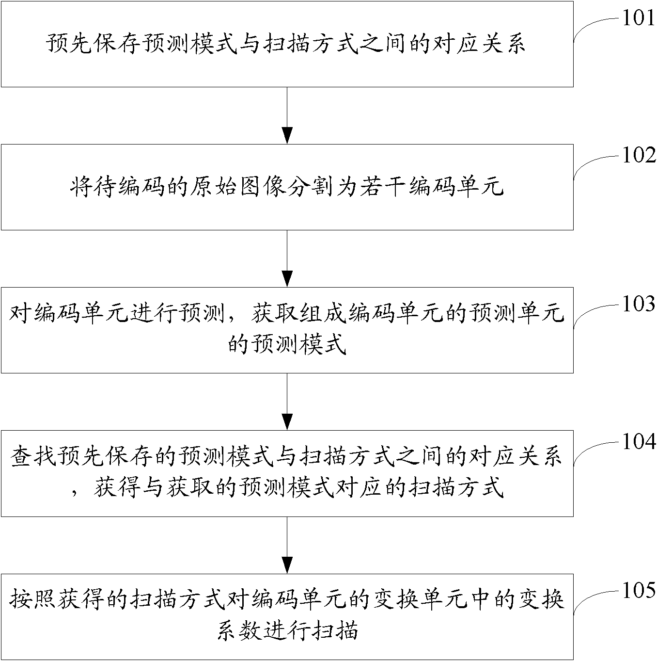
[0046] see Figure 1A , is the flow chart of the first embodiment of the transformation coefficient scanning method in the encoding of the present application:
[0047] Step 101: pre-save the corresponding relationship between the prediction mode and the scanning mode.
[0048] In the embodiment of the present application, for the image data to be encoded at the encoding end, because it is relatively large, it can be divided into several sub-data blocks for encoding respectively, and each sub-data block can be called a coding unit. The coded data is usually a matrix data, and the row and column values in the matrix data are consistent, that is, each coding unit is a square matrix data block. When encoding a coding unit, it is necessary to perform prediction on the coding unit to determine the prediction unit contained in the coding unit, and to perform transformation on the residual value to determine the transformation unit of the coding unit.
[0049] Such as Figure 1B ...
no. 1 example
[0099] see Figure 5 , is the block diagram of the first embodiment of the transformation coefficient scanning device in the encoding of the present application:
[0100] The device includes: a saving module 510 , a segmentation module 520 , a prediction module 530 , a search module 540 and a scanning module 550 .
[0101] Wherein, the saving module 510 is used to save the corresponding relationship between the prediction mode and the scanning mode;
[0102] A segmentation module 520, configured to segment the original image to be encoded into several coding units;
[0103] A prediction module 530, configured to predict the coding unit, and acquire prediction modes of the prediction units that make up the coding unit;
[0104] A search module 540, configured to search for the pre-saved correspondence, and obtain the scan mode corresponding to the acquired prediction mode;
[0105] The scanning module 550 is configured to scan the transform coefficients in the transform unit...
no. 2 example
[0106] see Image 6 , which is a block diagram of the second embodiment of the transformation coefficient scanning device in the coding of the present application:
[0107] The device includes: a saving module 610 , a segmentation module 620 , a prediction module 630 , a calculation module 640 , a determination module 650 , a transformation module 660 , a search module 670 and a scan module 680 .
[0108] Wherein, the saving module 610 is used to save the corresponding relationship between the prediction mode and the scanning mode;
[0109] A segmentation module 620, configured to segment the original image to be encoded into several coding units;
[0110] A prediction module 630, configured to predict the coding unit, and acquire prediction modes of the prediction units that make up the coding unit;
[0111] A calculation module 640, configured to calculate a residual value of the coding unit according to the original data of the coding unit and the predicted data after pre...
PUM
 Abstract
Description
Claims
Application Information
 - Generate Ideas
- Intellectual Property
- Life Sciences
- Materials
- Tech Scout
- Unparalleled Data Quality
- Higher Quality Content
- 60% Fewer Hallucinations
Browse by: Latest US Patents, China's latest patents, Technical Efficacy Thesaurus, Application Domain, Technology Topic, Popular Technical Reports.
© 2025 PatSnap. All rights reserved.Legal|Privacy policy|Modern Slavery Act Transparency Statement|Sitemap|About US| Contact US: help@patsnap.com