High-pressure pump

A high-pressure pump and pump piston technology, applied in pump components, pump control, fuel injection pumps, etc., can solve problems such as poor adjustability, mechanical vibration, high noise, etc., and achieve the effect of improving structure, compact structure, and improving efficiency

Inactive Publication Date: 2013-01-02
ROBERT BOSCH GMBH
View PDF7 Cites 10 Cited by
  • Summary
  • Abstract
  • Description
  • Claims
  • Application Information

AI Technical Summary

Problems solved by technology

These disadvantages are high noise, poor adjustability and mechanical vibrations based on cavitation occurring in the supply duct leading to the inlet valve
Pressure waves between the metering unit and the suction valve have a negative effect on the way of operation here

Method used


Image

  • High-pressure pump

Examples


Embodiment Construction

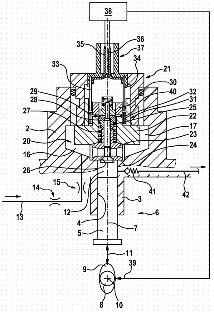
[0017] figure 1 A high-pressure pump 1 according to an embodiment of the invention is shown in a diagrammatic, schematic axial section. In particular, the high-pressure pump 1 can be designed as a radial or in-line piston pump. In particular, the high-pressure pump 1 is suitable as a fuel pump for a fuel injection system of an air-compressed, self-igniting internal combustion engine.

[0018] The high-pressure pump 1 is preferably used in fuel injection systems having a fuel distribution rail for storing high-pressure diesel fuel. However, the high-pressure pump 1 according to the invention is also suitable for other applications. In particular, the high-pressure pump can also be designed as a piston pump in order to deliver suitable liquids, ie also other liquids as fuel.

[0019] The high-pressure pump 1 has a pump housing, to which a cylinder head 2 is mounted. The cylinder head 2 has an attachment 3 which protrudes into a bore of the pump housing. Here, a cylinder bor...


PUM


Abstract

A high-pressure pump (1), which serves in particular as a radial or in-line piston pump for fuel injection systems of air-compressing, auto-ignition internal combustion engines, comprises a cylinder head (2) and a pump assembly (6). Here, the cylinder head (2) has a cylinder bore (4) in which a pump piston (5) of the pump assembly (6) is guided. Here, the pump piston (5) delimits, in the cylinder bore (4), a pump working chamber (12). Also provided is an inlet valve (20) which is integrated into the cylinder head (2) and via which fuel can be conducted into the pump working chamber (12). Metering of the fuel conducted into the pump working chamber (12) can be achieved by actuation of the inlet valve (20). Here, full charging of the pump working chamber (12) may take place. It is however also possible for partial charging of the pump working chamber (12) to be achieved by means of suitable actuation of the inlet valve (20).

Description

technical field [0001] The invention relates to a high-pressure pump, especially a radial or in-line piston pump. In particular, the invention relates to the field of fuel pumps for fuel injection systems of air-compressed, self-igniting internal combustion engines. However, the high-pressure pump can also be used as a piston pump for conveying other suitable liquids. Background technique [0002] A high-pressure fuel pump is known from DE 195 15 191 A1. The high-pressure fuel pump has a cylinder, the upper portion of which is exposed with respect to the exterior of the cylinder head, which is part of the engine housing. The remaining section of the high-pressure fuel is received in a seating hole of the cylinder head. A pump cam is mounted on the valve camshaft to drive the intake / discharge valves, and drives the high pressure fuel pump. The accuracy for controlling the fuel delivery is additionally improved since the time characteristic curve by which the fuel at high ...

Claims


Application Information

Patent Timeline
Patent Type & Authority Applications(China)
IPC IPC(8): F02M59/48F04B53/00F02M55/04F02M59/10F02M59/36F04B53/22F04B53/10
CPCF02M59/366F04B49/225F04B53/10F02M59/102F02M2200/315F04B53/22F02D41/3845F02M59/48F02M59/466F02M55/04F04B53/007F02M59/367F02M63/0035
Inventor N·罗德里格斯-阿马亚P·伯兰德W·富克斯A·蒂尔曼U·伊本
Owner ROBERT BOSCH GMBH
Why Eureka
Try Eureka