Base assembly for floor cleaner

A cleaner and floor technology, which is applied in the direction of cleaning floors, cleaning equipment, machine parts, etc., can solve the problems of complex structure, expensive bearings, etc., and achieve the effect of reducing height

Inactive Publication Date: 2013-01-09
SUZHOU HAAN TECH +1
View PDF10 Cites 20 Cited by
  • Summary
  • Abstract
  • Description
  • Claims
  • Application Information

AI Technical Summary

Problems solved by technology

[0012] Bearings can support weight, and at the same time help smooth forward and backward linear reciprocating motion, but for the bearings, a sliding structure should be added and assembled with each other, not only the structure is complicated, but more importantly, the price of the bearings is very expensive

Method used


Image

  • Base assembly for floor cleaner
  • Base assembly for floor cleaner
  • Base assembly for floor cleaner

Examples


Embodiment Construction

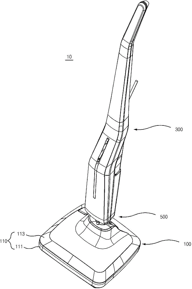
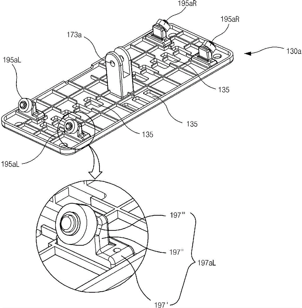
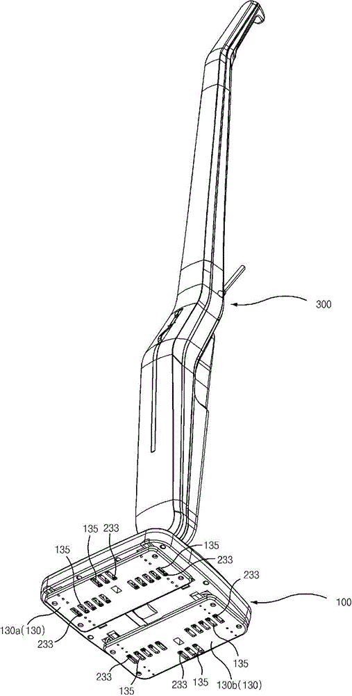
[0073] Hereinafter, preferred embodiments of the present invention will be described in detail with reference to the accompanying drawings. figure 1 is a front perspective view showing a floor cleaner according to a preferred embodiment of the present invention, figure 2 yes figure 1 The upward perspective view of image 3 and Figure 4 It is a front and bottom exploded perspective view of a base assembly for a floor cleaner according to a preferred embodiment of the present invention, Figure 5 and Figure 6 It is an exploded and combined perspective view showing the main parts, Figure 7 is an isolated perspective view of a drive part and a mounting case according to a preferred embodiment of the present invention, Figure 8 is a bottom view showing a base assembly for a floor cleaner according to a preferred embodiment of the present invention, Figure 9 is intercepted Figure 8 The section view seen on line 9-9 or 9'-9', Figure 10 yes image 3 A magnified isomet...


PUM


Abstract

The present invention relates to a base assembly for a floor cleaner, which cleans a floor through that two rag-adhered pads mutually approach and move back to perform a straight reciprocating motion; in particular to a base assembly for a floor cleaner, which performs floor wiping and sterilization through spraying steam to the rag-adhered pads to perform reciprocating motion.

Description

technical field [0001] The present invention relates to a base assembly for a floor cleaner that cleans the floor by linear reciprocating motions of two mop attachment pads approaching and retreating from each other, and more particularly to a base assembly for cleaning the floor by spraying steam to the mop attachment pads that are reciprocating. Base assembly for wiping and disinfecting floor cleaners. Background technique [0002] As the publications described in the patent documents, there is proposed a conventional floor cleaner that cleans the floor by linearly reciprocating the facing mop attachment pads. [0003] According to the main body of the floor cleaner in the patent document, it includes: a supporting part; a driving part, which is located on the upper part of the supporting part; a power conversion part, which converts the rotational motion provided by the driving part into the power required for linear reciprocating motion; the moving part , which is locat...

Claims


Application Information

Patent Timeline
Patent Type & Authority Applications(China)
IPC IPC(8): A47L11/40
CPCA47L11/12A47L13/225A47L11/4069A47L11/4036A47L11/284
Inventor 韩京姬
Owner SUZHOU HAAN TECH
Why Eureka
Try Eureka