Transverse numerical control polishing method for blade profile

A blade and horizontal technology, which is applied in the field of horizontal CNC polishing of the blade surface, can solve the problems of unsatisfactory polishing effect, low polishing efficiency, obvious longitudinal grain of the blade, etc., achieve stable surface quality, improve effect and precision, and eliminate transverse vibration lines Effect

Inactive Publication Date: 2013-01-09
NORTHWESTERN POLYTECHNICAL UNIV
View PDF10 Cites 2 Cited by
  • Summary
  • Abstract
  • Description
  • Claims
  • Application Information

AI Technical Summary

Problems solved by technology

[0006] In order to solve the problems of obvious longitudinal grains after blade polishing, unsatisfactory polishing effect a

Method used


Image

  • Transverse numerical control polishing method for blade profile
  • Transverse numerical control polishing method for blade profile
  • Transverse numerical control polishing method for blade profile

Examples


Embodiment 1

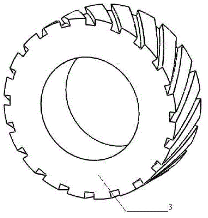
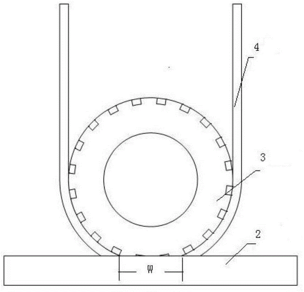
[0024] Step 1: Refer to attached figure 2 , choose a contact wheel with a hardness of 50HS. There is a chute on the contact surface of the contact wheel. The angle between the chute and the axial direction of the contact wheel is 60°; the diameter of the contact wheel is 60mm, the wheel width is 30mm, and the groove width is 5mm. The spacing is 5mm. What is used here is a soft contact wheel. The so-called soft contact wheel means that after a certain pressure is applied to the polishing wheel, the polishing wheel will be deformed, causing the abrasive belt point polishing to become surface polishing, such as image 3 As shown, the soft contact wheel is used for polishing with close row spacing in the transverse direction. The soft contact wheel can obviously eliminate the transverse vibration pattern, and the overlapping degree of transverse polishing is smaller than that of longitudinal polishing.

[0025] Step 2: Planning CNC polishing trajectory:

[0026] Step 2.1: Estab...

Embodiment 2

[0032] Step 1: Refer to attached figure 2 , choose a contact wheel with a hardness of 35HS. There is a chute on the contact surface of the contact wheel. The angle between the chute and the axial direction of the contact wheel is 30°; the diameter of the contact wheel is 50mm, the wheel width is 20mm, and the groove width is 4mm. The spacing is 4mm. What is used here is a soft contact wheel. The so-called soft contact wheel means that after a certain pressure is applied to the polishing wheel, the polishing wheel will be deformed, causing the abrasive belt point polishing to become surface polishing, such as image 3As shown, the soft contact wheel is used for polishing with close row spacing in the transverse direction. The soft contact wheel can obviously eliminate the transverse vibration pattern, and the overlapping degree of transverse polishing is smaller than that of longitudinal polishing.

[0033] Step 2: Planning CNC polishing trajectory:

[0034] Step 2.1: Establ...

Embodiment 3

[0040] Step 1: Refer to attached figure 2 , choose a contact wheel with a hardness of 45HS. There is a chute on the contact surface of the contact wheel. The angle between the chute and the axial direction of the contact wheel is 35°; the diameter of the contact wheel is 50mm, the wheel width is 20mm, and the groove width is 4mm. The pitch is 4mm. What is used here is a soft contact wheel. The so-called soft contact wheel means that after a certain pressure is applied to the polishing wheel, the polishing wheel will be deformed, causing the abrasive belt point polishing to become surface polishing, such as image 3 As shown, the soft contact wheel is used for polishing with close row spacing in the transverse direction. The soft contact wheel can obviously eliminate the transverse vibration pattern, and the overlapping degree of transverse polishing is smaller than that of longitudinal polishing.

[0041] Step 2: Planning CNC polishing trajectory:

[0042] Step 2.1: Establi...


PUM

PropertyMeasurementUnit
Hardnessaaaaaaaaaa

Abstract

The invention provides a transverse numerical control polishing method for a blade profile. The polishing method comprises the following steps: firstly selecting a soft contact wheel, wherein a chute is arranged on the contact surface of the contact wheel, and the included angle of the chute and the axial direction of the contact wheel ranges from 30 degrees to 60 degrees; and then planning numerical control polishing track, finally polishing a blade, enabling the contact wheel to move along the direction of a self axis in polishing, wherein the soft contact wheel is adopted, the polishing wheel changes point polishing of a profile sand belt into plane polishing after being applied by certain pressure, so that transverse chatter mark can be obviously eliminated, the surface quality of the blade is stable, the polishing effect and precision can be greatly improved, and the method not only can be used for polishing the blade, but also can be used for polishing the blade of the whole bladed disk.

Description

technical field [0001] The invention relates to the technical field of mechanical processing of engine blades, in particular to a transverse numerical control polishing method for blade profiles. Background technique [0002] Aeroengine blades must bear huge centrifugal force and complex starting force and vibration during work, and are also subjected to thermal stress. The working environment is relatively harsh. Its function and operating conditions in the engine determine the shape of the blade in the engine Complex, wide-ranging, and heaviest-loaded parts. Therefore, the blade needs to be polished to obtain a higher surface quality in order to improve its performance. [0003] However, due to the development of the blade structure in the direction of large, thin, complex curvature, various types, and high quality requirements, this has brought severe challenges to the polishing technology of the blade. The main problem is the contradiction between blade processing defor...

Claims


Application Information

Patent Timeline
IPC IPC(8): B24B1/00
Inventor 蔺小军史耀耀赵涛杨阔董婷吴广段继豪张军锋
Owner NORTHWESTERN POLYTECHNICAL UNIV
Why Eureka
Try Eureka