Transverse numerical control polishing method for blade profile
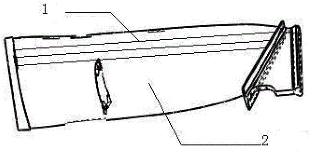
A blade and horizontal technology, which is applied in the field of horizontal CNC polishing of the blade surface, can solve the problems of unsatisfactory polishing effect, low polishing efficiency, and obvious longitudinal grain of the blade, so as to achieve stable surface quality, improve effect and precision, and eliminate transverse vibration lines Effect
- Summary
- Abstract
- Description
- Claims
- Application Information
AI Technical Summary
Problems solved by technology
Method used
Image
Examples
Embodiment 1
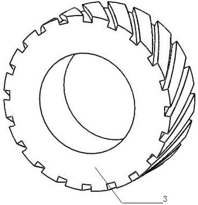
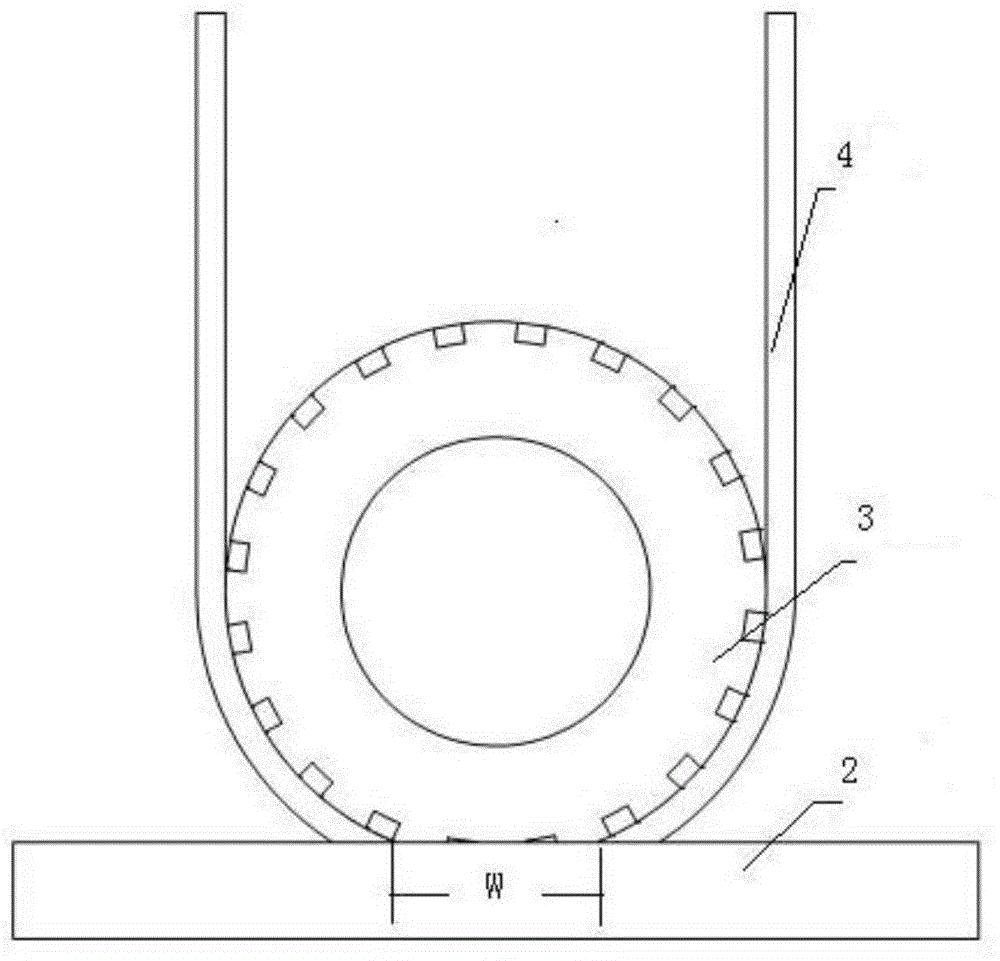
[0024] Step 1: Refer to attached figure 2 , choose a contact wheel with a hardness of 50HS. There is a chute on the contact surface of the contact wheel. The angle between the chute and the axial direction of the contact wheel is 60°; the diameter of the contact wheel is 60mm, the wheel width is 30mm, and the groove width is 5mm. The spacing is 5mm. What is used here is a soft contact wheel. The so-called soft contact wheel means that after a certain pressure is applied to the polishing wheel, the polishing wheel will be deformed, causing the abrasive belt point polishing to become surface polishing, such as image 3 As shown, the soft contact wheel is used for polishing with close row spacing in the transverse direction. The soft contact wheel can obviously eliminate the transverse vibration pattern, and the overlapping degree of transverse polishing is smaller than that of longitudinal polishing.
[0025] Step 2: Planning CNC polishing trajectory:
[0026] Step 2.1: Estab...
Embodiment 2
[0032] Step 1: Refer to attached figure 2 , choose a contact wheel with a hardness of 35HS. There is a chute on the contact surface of the contact wheel. The angle between the chute and the axial direction of the contact wheel is 30°; the diameter of the contact wheel is 50mm, the wheel width is 20mm, and the groove width is 4mm. The spacing is 4mm. What is used here is a soft contact wheel. The so-called soft contact wheel means that after a certain pressure is applied to the polishing wheel, the polishing wheel will be deformed, causing the abrasive belt point polishing to become surface polishing, such as image 3As shown, the soft contact wheel is used for polishing with close row spacing in the transverse direction. The soft contact wheel can obviously eliminate the transverse vibration pattern, and the overlapping degree of transverse polishing is smaller than that of longitudinal polishing.
[0033] Step 2: Planning CNC polishing trajectory:
[0034] Step 2.1: Establ...
Embodiment 3
[0040] Step 1: Refer to attached figure 2 , choose a contact wheel with a hardness of 45HS. There is a chute on the contact surface of the contact wheel. The angle between the chute and the axial direction of the contact wheel is 35°; the diameter of the contact wheel is 50mm, the wheel width is 20mm, and the groove width is 4mm. The pitch is 4mm. What is used here is a soft contact wheel. The so-called soft contact wheel means that after a certain pressure is applied to the polishing wheel, the polishing wheel will be deformed, causing the abrasive belt point polishing to become surface polishing, such as image 3 As shown, the soft contact wheel is used for polishing with close row spacing in the transverse direction. The soft contact wheel can obviously eliminate the transverse vibration pattern, and the overlapping degree of transverse polishing is smaller than that of longitudinal polishing.
[0041] Step 2: Planning CNC polishing trajectory:
[0042] Step 2.1: Establi...
PUM
 Abstract
Description
Claims
Application Information
 - R&D
- Intellectual Property
- Life Sciences
- Materials
- Tech Scout
- Unparalleled Data Quality
- Higher Quality Content
- 60% Fewer Hallucinations
Browse by: Latest US Patents, China's latest patents, Technical Efficacy Thesaurus, Application Domain, Technology Topic, Popular Technical Reports.
© 2025 PatSnap. All rights reserved.Legal|Privacy policy|Modern Slavery Act Transparency Statement|Sitemap|About US| Contact US: help@patsnap.com


