
Method for determining slip factors of centrifugal pump on basis of internal flow measurement under all conditions

A slip coefficient and determination method technology, applied in pump control, non-variable pump, machine/engine, etc., can solve problems affecting the real flow at the outlet of the impeller

Active Publication Date: 2015-04-22
JIANGSU UNIV
View PDF5 Cites 2 Cited by
  • Summary
  • Abstract
  • Description
  • Claims
  • Application Information

AI Technical Summary

Problems solved by technology

Fluid Engineering "Slip Coefficient of Ultra-short-blade Centrifugal Pump Impeller" (No. 6, 1991) used a three-hole cylindrical probe to measure the absolute velocity of the liquid at the outlet of the ultra-short-blade centrifugal pump impeller, and studied the blade on this basis. The effect of the outlet placement angle on the slip coefficient of the long and short blades, but the probe affects the real flow at the outlet of the impeller

Method used


Image

  • Method for determining slip factors of centrifugal pump on basis of internal flow measurement under all conditions
  • Method for determining slip factors of centrifugal pump on basis of internal flow measurement under all conditions
  • Method for determining slip factors of centrifugal pump on basis of internal flow measurement under all conditions

Examples


Embodiment

[0023] (1) PIV experiments are used to measure the internal unsteady flow laws of centrifugal pumps under three working conditions.

[0024] For a double-vane centrifugal pump with a specific speed of 115.6, its performance parameters under three working conditions are: 0.8 times the design working condition Q 1 =27.56m 3 / h, H 1 =4.96m, n 1 =56.32%; design conditions Q 2 =34.48m 3 / h, H 2 =4.50m, n 2 =58.48%; 1.2 times design conditions Q 3 =41.40m 3 / h, H 3 =4.03m, n 3 =57.89%.

[0025] 1) Selection of measurement area and tracer particles.

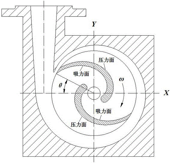
[0026] Select the middle section of the impeller as the measurement plane, such as figure 2 shown. The impeller rotates clockwise at a speed of 1000r / min, facing the suction surface of the blade at the tongue X Angle between axes θ =28°. Six different phases are measured in each working condition, which are recorded as φ / 6, φ / 3, φ / 2, 2 φ / 3,5 φ / 6, φ , with a phase difference of 30°.

[0027...


PUM


Abstract

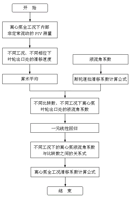
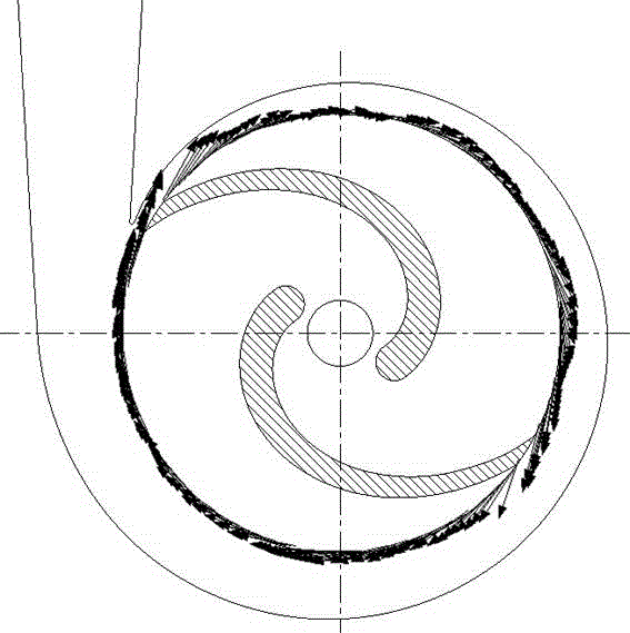
The invention discloses a method for determining slip factors of a centrifugal pump on the basis of internal flow measurement under all conditions. The method includes measuring internal non-steady flow laws of the centrifugal pump under different conditions by PIV (particle image velocimetry) experiments; obtaining an average slip speed of an outlet of an impeller of the centrifugal pump under the different conditions by an arithmetic method on the basis of absolute speed distribution obtained by the PIV experiments and computing slip factors of the centrifugal pump under the different conditions; computing angle factors of liquid flows of the centrifugal pump under the different conditions; performing PIV measurement for internal flow of the centrifugal pump at different specific speeds to obtain angle factors of liquid flows at different specific speeds and under different conditions; and creating relation between the angle factors of the liquid flows and the specific speeds under the different conditions by unary linear regression so as to determining a computational formula of the slip factors of the centrifugal pump under the different conditions. The method has the advantages that the slip factors of the centrifugal pump under the different conditions can be accurately computed, and energy conservation transformation for an existing pump can be carried out by a centrifugal pump energy and performance computational formula created on the basis of the method.

Description

technical field [0001] The invention belongs to the field of energy performance calculation of a centrifugal pump, and in particular relates to a method for determining the slip coefficient of a centrifugal pump based on internal flow measurement in all working conditions. Background technique [0002] At present, the commonly used slip coefficient calculation formulas mainly include Stodola formula, Wiesnell formula, and Pfleder formula. The Stodola formula and the Wiesner formula only consider the influence of the axial vortex on the relative motion of the outlet, and the Pfleder formula assumes that the flow of the liquid in the impeller does not deviate. Compared with the real flow of the fluid in the impeller, these three formulas do not consider the influence of the liquid flow angle, and the calculated slip coefficient has certain errors. With the rapid development of social economy, many centrifugal pumps must meet the performance requirements of multiple working co...

Claims


Application Information

Patent Timeline
Patent Type & Authority Patents(China)
IPC IPC(8): F04D15/00
Inventor 刘厚林王凯袁寿其谈明高王勇董亮周孝华
Owner JIANGSU UNIV
Learn More