Electric switch having a slider and forming a break switch or changeover switch

A technology of electric switches and sliders, applied in the field of electric switches, can solve problems such as poor contact, loosening of screwed connections, failure to ensure sufficient and reliable electrical contact, etc.

Inactive Publication Date: 2015-09-16
ARIANEGRP SAS
View PDF9 Cites 0 Cited by
  • Summary
  • Abstract
  • Description
  • Claims
  • Application Information

AI Technical Summary

Problems solved by technology

This screwed connection does not ensure a sufficiently reliable electrical contact between the slider and the conductive post
Under the action of external stress (vibration, shock, etc.), the screwed connection can become loose, resulting in poor contact, arcing and other undesirable phenomena

Method used


Image

  • Electric switch having a slider and forming a break switch or changeover switch
  • Electric switch having a slider and forming a break switch or changeover switch
  • Electric switch having a slider and forming a break switch or changeover switch

Examples


Embodiment Construction

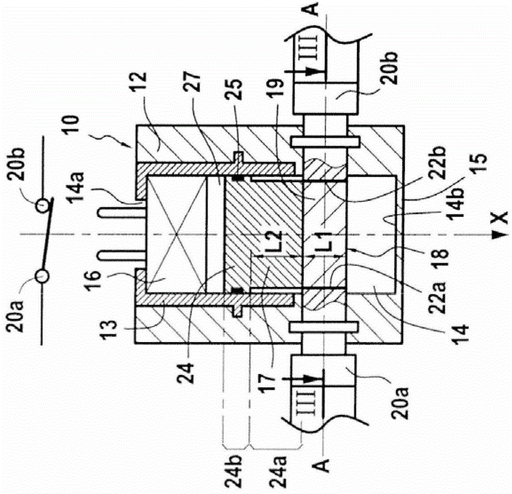
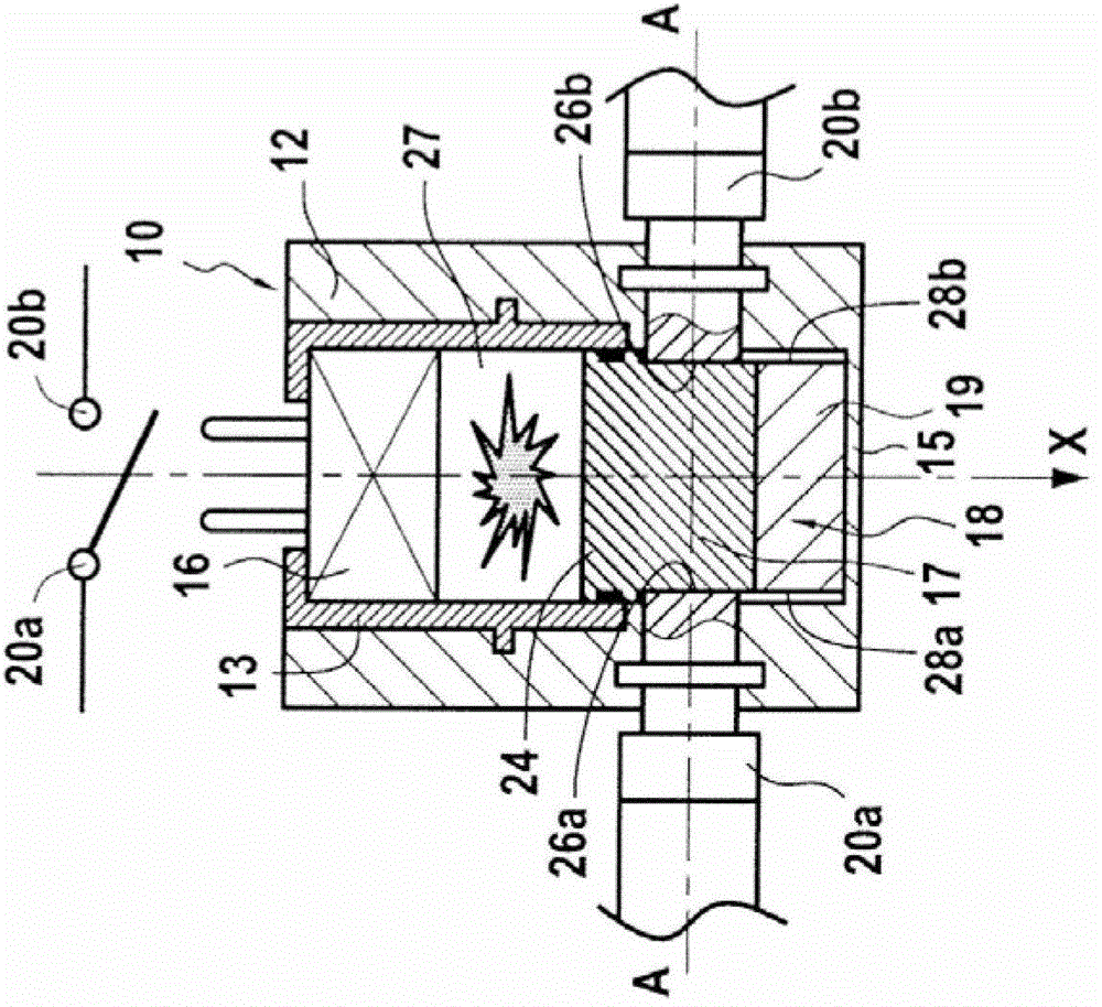
[0031] In an example, the electrical switch of the invention comprises a hollow body 12 defining an inner cavity 14 of circular section with a bottom end 14b closed by a bottom wall 15 ; and an upper part of the hollow body 12 is lined by a cover 13 . In other embodiments, cavity 14 may of course exhibit a rectangular or any other suitable shaped cross-section.

[0032] In this description, unless stated otherwise, the axial direction is a direction parallel to the main axis X of the cavity 14 of the hollow body 12 . Also, the radial direction is a direction perpendicular to the main axis X of the cavity 14 and intersecting said axis. Unless stated to the contrary, the adjectives and adverbs "axial", "radial", "axially" and "radially" are used with reference to the above axial and radial directions. Likewise, an axial plane is a plane containing the main axis X of the cavity 14 and a radial plane is a plane perpendicular to said axis. Similarly, an axial section is a section...


PUM


Abstract

The present invention relates to an electric switch having a hollow body defining a cavity, an actuator, and a slide mounted in said cavity. Under the action of the actuator, the slide is suitable for passing from a first position, in which at least one conductive portion of the slide is electrically connected via permanent breakable electrical junctions to at least two primary electrically-conductive studs that lead laterally into said cavity to a second position in which at least one of said primary electrically-conductive studs is no longer electrically connected to said conductive portion of the slide.

Description

technical field [0001] The invention relates to an electric switch. [0002] More specifically, the present invention relates to an electrical switch having a "slider", in particular to an electrical switch of the type comprising: a hollow body defining a cavity; an actuator arranged in said cavity a slider, which is installed in the chamber downstream of the actuator, and which includes at least one conductive part; and at least two main conductive posts, which are arranged in the thickness of the hollow body and are viewed from the transverse into the cavity; when the slider is in the first position, the conductive part of the slider and the two main conductive columns are electrically connected to each other, thereby closing the first circuit; and the slider is adapted to move from the first The position is advanced to a second position in which at least one of the main conductive posts is no longer electrically connected to the conductive portion of the slider. [0003] ...

Claims


Application Information

Patent Timeline
Patent Type & Authority Patents(China)
IPC IPC(8): H01H39/00
CPCH01H39/006H01H39/004H01H15/06
Inventor 埃夫拉尔·博格
Owner ARIANEGRP SAS
Why Eureka
Try Eureka