
Method for manufacturing contact and metal part

A manufacturing method and technology of metal parts, applied in the direction of contact manufacturing, contact parts, connection, etc., can solve the problem that the contact 21 cannot be eliminated gradually loosening and falling off

Active Publication Date: 2015-12-16
OMRON CORP
View PDF4 Cites 0 Cited by
  • Summary
  • Abstract
  • Description
  • Claims
  • Application Information

AI Technical Summary

Problems solved by technology

[0006] Therefore, in this connector 11, the situation that the contact piece 21 is drawn out from the housing and gradually loosens and falls off cannot be eliminated.

Method used


Image

  • Method for manufacturing contact and metal part
  • Method for manufacturing contact and metal part
  • Method for manufacturing contact and metal part

Examples


Embodiment Construction

[0069] Hereinafter, preferred embodiments of the present invention will be described with reference to the drawings. However, the present invention is not limited to the following embodiments, and various design changes can be made without departing from the gist of the present invention.

[0070] (Structure of Contacts)

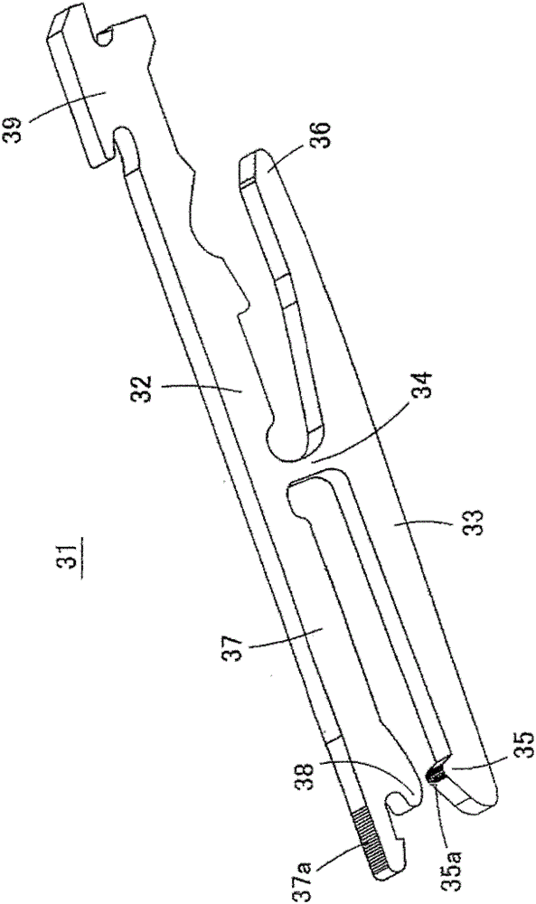
[0071] image 3 It is a perspective view of the contact 31 which concerns on one Embodiment of this invention, and is shown in the state turned upside down. The contacts 31 are minute connection terminals produced by electroforming. Figure 4 (A) and Figure 4 (B) is an enlarged view of a part of the contact 31 . in addition, Figure 5 (A) is a sectional view of the connector 51 assembled into the contact 31, Figure 5 (B) is a sectional view of the connector 51 to which the flexible printed circuit board 46 is connected.

[0072] The fixed piece 32 and the movable piece 33 of the contact piece 31 are substantially parallel, and the fixed piece 32 and...


PUM

PropertyMeasurementUnit
widthaaaaaaaaaa
radiusaaaaaaaaaa

Abstract

A method for manufacturing a contact piece and a metal part, capable of reliably making electrical contact and mechanical contact with other parts. The contact piece (31) connects the fixed piece (32) and the movable piece (33) which are substantially parallel with each other through a connecting portion (34). The lower surface of the front end of the movable piece (33) is provided with a movable contact portion (35) for contacting with a flexible printed circuit board, etc., and a movable contact portion (35) is provided on the rear end of the movable piece (33). The movable piece (33) is inclined to operate the receiving part (36). The front end portion of the fixing piece (32) is a fitting portion (37) for fitting with the housing of the connector. On the contact (31), a contact contact surface (35a) serving as a contact surface of the movable contact portion (35) is provided with concavo-convex shapes extending in the width direction of the contact (31). In addition, the lower surface of the fitting portion (37) is a contact surface with the crimping surface (37a), that is, the bottom surface of the housing, and the crimping surface (37a) is also provided with a of concave-convex shape.

Description

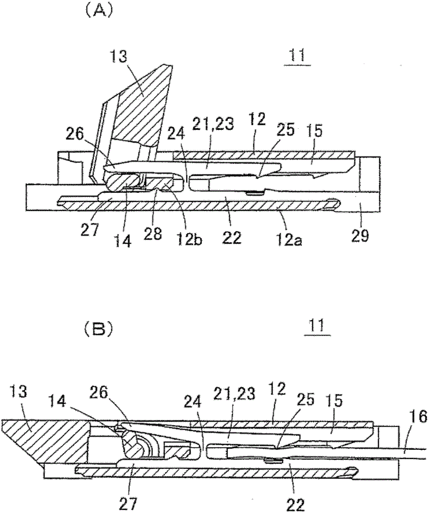
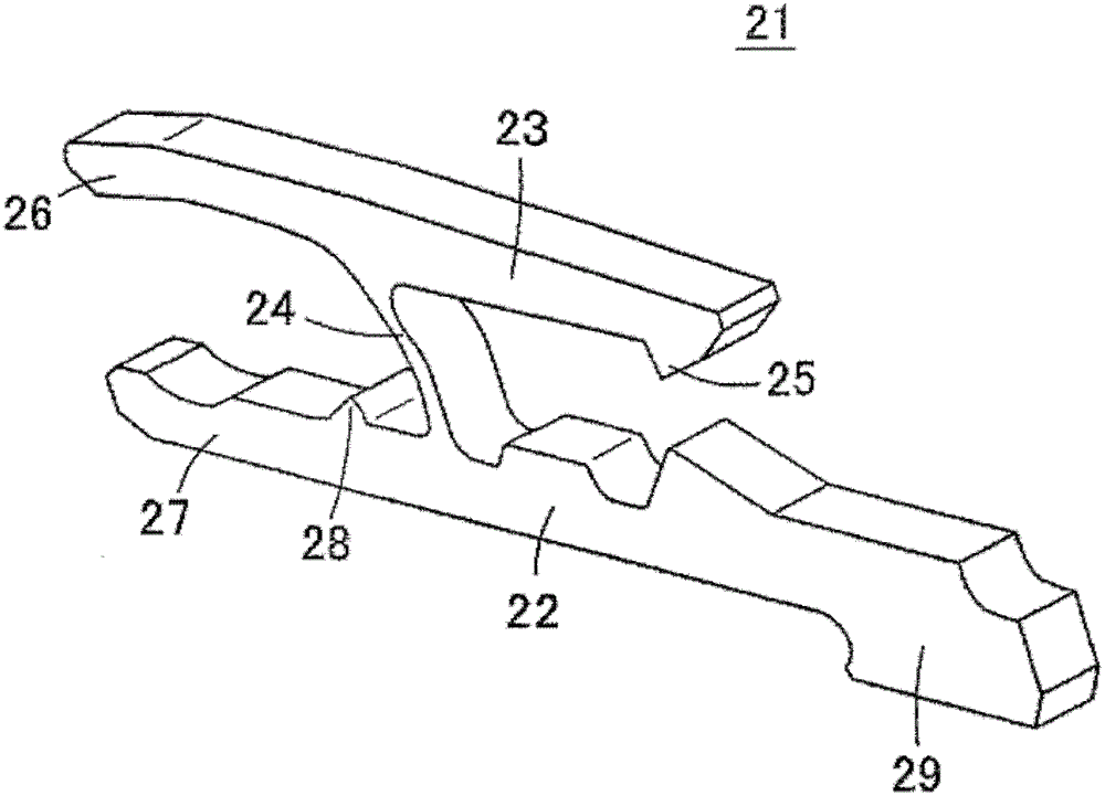
technical field [0001] The invention relates to a method of manufacturing a contact piece and a metal part. For example, it relates to a method of manufacturing a contact that is incorporated into a housing to form a connector and a metal member that can be used to manufacture the contact. Background technique [0002] Disclosed in Patent Document 1 as figure 1 (A) and figure 1 (B) Connector with the configuration shown. Two types of contacts (connection terminals) are assembled in the housing 12 of the connector 11 . figure 2 A contact piece 21 is indicated. The fixed piece 22 and the movable piece 23 of the contact piece 21 are substantially parallel, and the fixed piece 22 and the movable piece 23 are connected by a connecting portion 24 perpendicular to the two pieces 22 , 23 . A movable contact portion 25 is provided on the lower surface of the front end portion of the movable piece 23 , and the rear end portion of the movable piece 23 serves as an operation recei...

Claims


Application Information

Patent Timeline
Patent Type & Authority Patents(China)
IPC IPC(8): H01R13/04H01R13/11H01R43/16H01R12/72
CPCH01R12/778H01R12/88H01R12/77H01R43/16
Inventor 吉田仁吉冈秀和铃村宜晓小山次郎
Owner OMRON CORP
Learn More