

Plug-in circuit breaker assembly
Patent Information
- Authority / Receiving Office
- CN · China
- Current Assignee / Owner
- 雷比诺有限责任公司
- Publication Date
- 2013-01-09
Smart Images
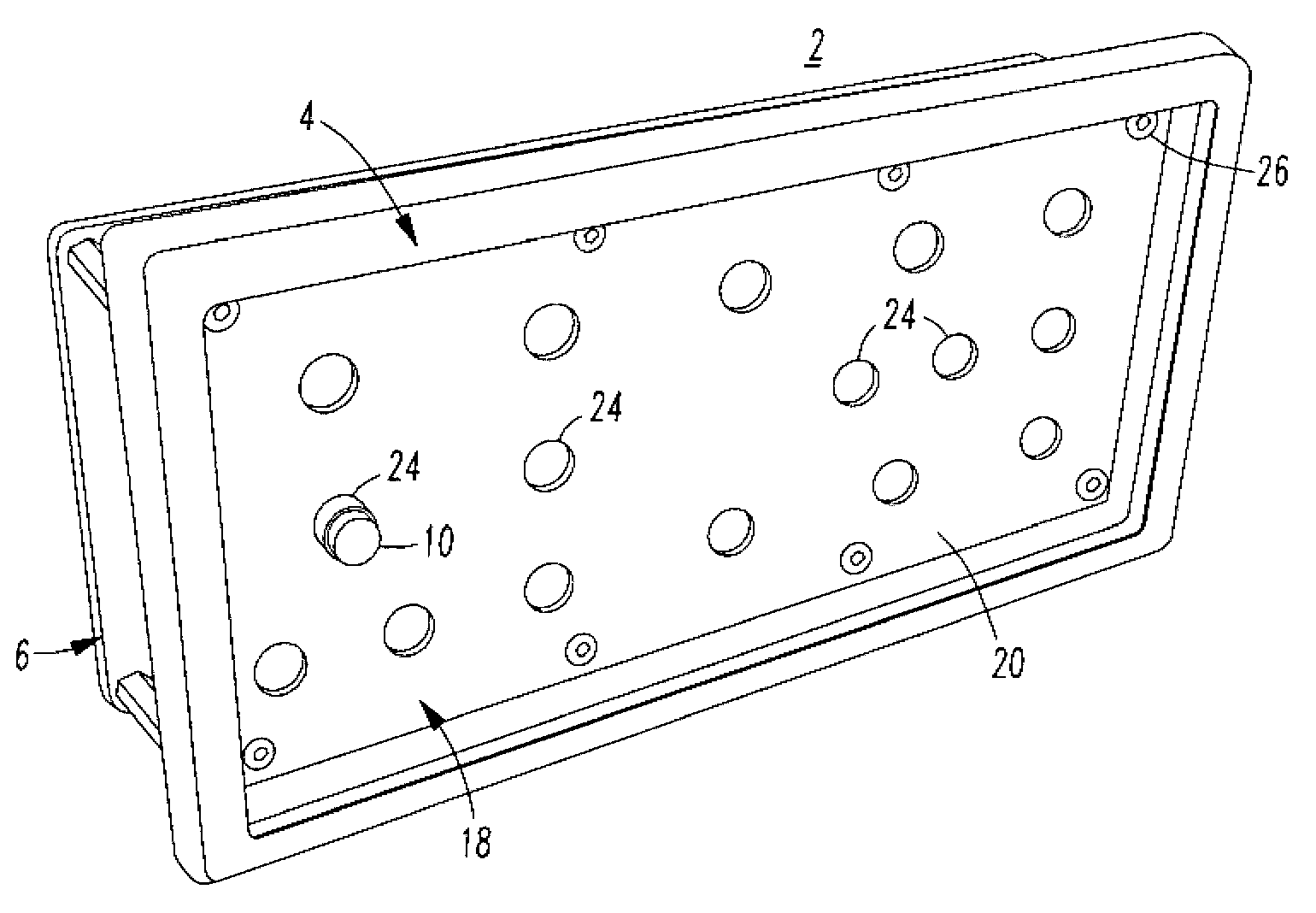
Figure 1 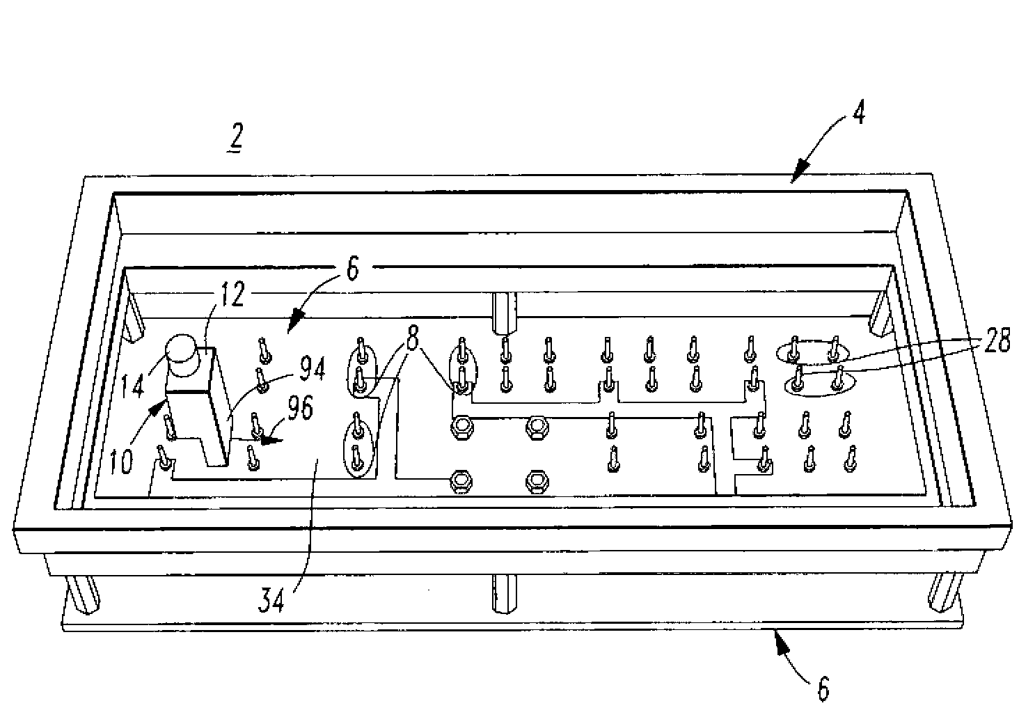
Figure 2 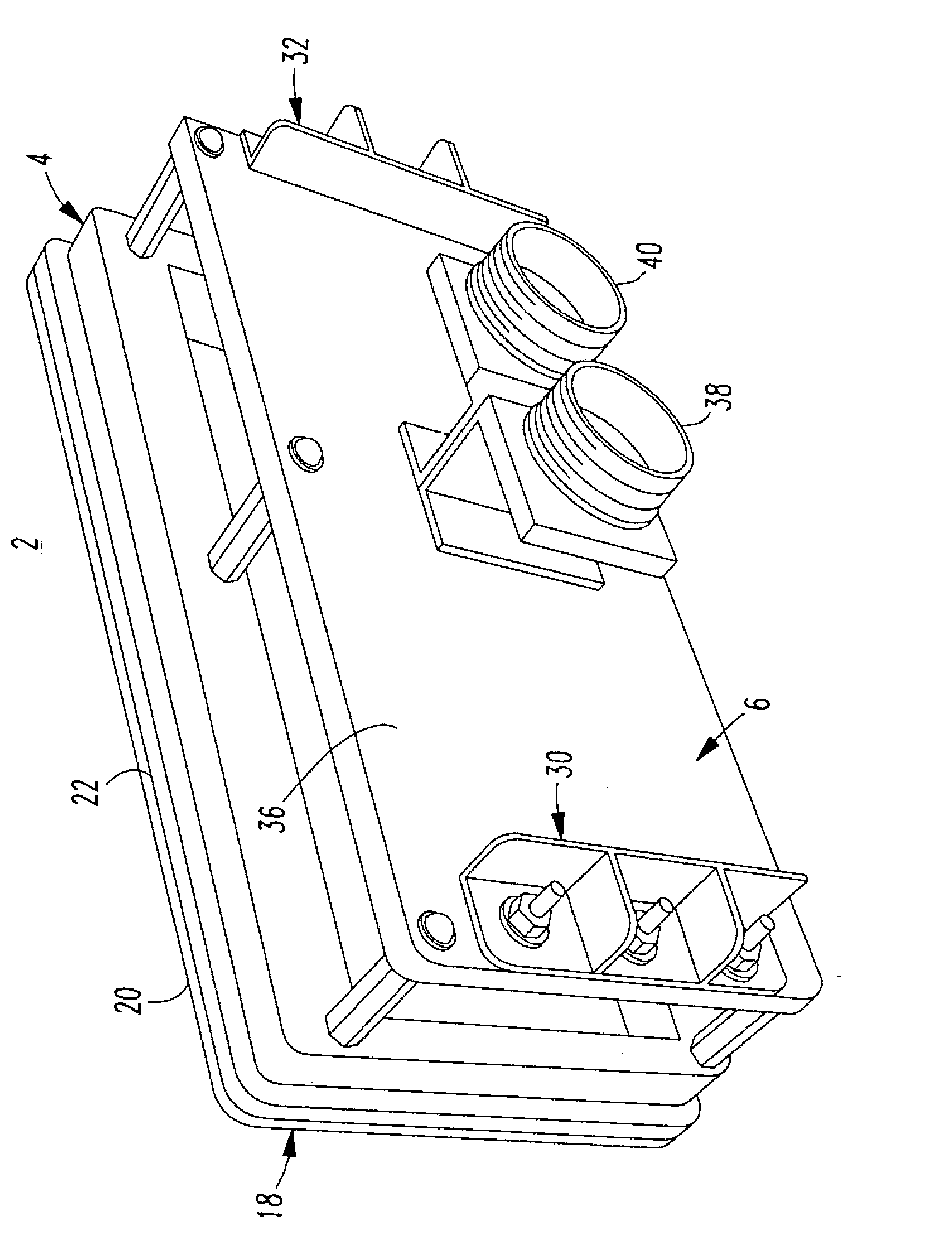
Figure 3
Abstract
Description
technical field
[0001] The concepts disclosed herein relate generally to circuit breakers, and more particularly to circuit breaker assemblies, such as circuit breaker panels for many circuit breakers. Background technique
[0002] Circuit breakers are used, for example, in aircraft electrical systems not only to provide overcurrent protection but also as switches for switching devices on and off. Aircraft or subminiature circuit breakers, for example, are typically smaller to accommodate higher density layouts of aircraft circuit breaker panels that provide user access to circuit breakers for many circuits. An aircraft electrical system may, for example, consist of hundreds of circuit breakers, each for circuit protection functions and circuit disconnection functions by push-pull handles.
[0003] The push-pull handle of the circuit breaker moves from the inside to the outside to disconnect the corresponding load circuit. This action can be manual, or automatic in the eve...