an expansion valve

一种膨胀阀、阀芯的技术,应用在机械设备、流体循环安排、制冷组件等方向,能够解决增加空调机能耗、增加制冷剂阻力、降低使用寿命等问题,达到减少频繁动作、提高使用寿命、提高寿命的效果

Active Publication Date: 2014-10-15
ZHEJIANG ZESHUN REFRIGERATION TECH CO LTD
View PDF1 Cites 0 Cited by
  • Summary
  • Abstract
  • Description
  • Claims
  • Application Information

AI Technical Summary

Problems solved by technology

In reverse circulation, it can only flow through the orifice on the valve core, and the diameter of the valve cannot be changed, which increases unnecessary resistance when the refrigerant circulates and increases the energy consumption of the air conditioner.
And when reversed, the orifice is blocked by the movable part, and the valve core must be pushed open to flow, which causes the valve core to frequently impact under the force of the spring, reducing the service life of the valve

Method used


Image

  • an expansion valve
  • an expansion valve
  • an expansion valve

Examples


Embodiment 1

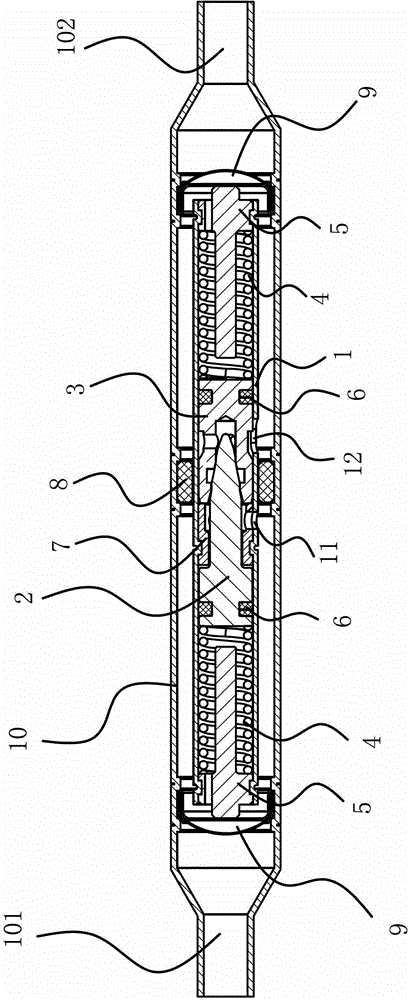
[0039] Such as figure 1 As shown, the expansion valve includes a casing 10 having an inlet port 101 and an outlet port 102. A straight cylindrical valve body 1 with an inner cavity is fixed inside the outer casing 10, and a valve body 1 is provided on the side wall to communicate with the inner cavity and the outer casing 10. The inlet 11 and the outlet 12, a spacer 8 is provided between the shell 10 and the valve body 1 to isolate the inlet 11 and the outlet 12, and the inner cavity is provided with a valve core one 2 and a valve core two 3 that can slide along the inner cavity, A retaining ring 7 is fixed in the middle of the inner cavity between the valve core one 2 and the valve core two 3, and the two ends of the inner cavity are respectively provided with spring assemblies that make the valve core one 2 and the valve core two 3 have a tendency to move toward the retaining ring 7, the valve A damping structure capable of buffering the first valve core 2 and the second val...

Embodiment 2

[0051] The structure and principle of embodiment two are basically similar to embodiment one, as Figure 6 As shown, the difference from Embodiment 1 lies in the addition of a small flow guide track structure. The structure of the small flow diversion track is that the valve core 2 3 is provided with a through hole 34 communicating with the outside of the valve body 1 and the hollow groove 33, and the through hole 34 is inlaid with a capillary. The flow rate of the through hole 34 can be changed by adding a capillary.

Embodiment 3

[0053] The structure and principle of embodiment three are basically similar to embodiment two, as Figure 7 As shown, the difference from the second embodiment lies in the structure of the small flow diversion track. The small flow diversion track structure is that the valve core one 2 is provided with a diversion groove 27 which can communicate with the hollow groove 33 and the front cylindrical hole 36 .


PUM


Abstract

The invention provides an expansion valve, which belongs to the technical field of air conditioning. It solves the problem that the valve core of the existing expansion valve frequently impacts under the force of the spring and reduces the service life of the valve. The expansion valve includes a shell with an inlet end and an outlet end, and a straight cylindrical valve body with an inner cavity is fixed inside the outer shell, and an inlet and an outlet connecting the inner cavity and the outer shell are opened on the side wall of the valve body, between the outer shell and the valve body There is a spacer that separates the inlet from the outlet, and the inner cavity is provided with a valve core 1 and a valve core 2 that can slide along the inner cavity and are paired with each other. Retaining ring, the two ends of the inner cavity are respectively equipped with spring components that make the spool 1 and spool 2 have a tendency to move towards the retaining ring, and there is a buffer between the spool 1 and spool 2 that can buffer The active damping structure. Due to the existence of the damping structure, there is a buffering process when the valve core 1 is close to the valve core 2, which reduces the impact between the valve cores and improves the life of the expansion valve.

Description

technical field [0001] The invention belongs to the technical field of air conditioners and relates to a mechanical automatic expansion valve for refrigeration of frequency conversion air conditioners. Background technique [0002] The expansion valve is an important part in the refrigeration system, generally installed between the condenser and the evaporator. The expansion valve can make the gas evaporated by the evaporator pressurized and liquefied into a high-temperature and high-pressure liquid refrigerant through the compressor, and throttling through its orifice to become a low-temperature and low-pressure mist liquid refrigerant, and then the refrigerant absorbs in the evaporator The heat achieves the cooling effect. The expansion valve controls the flow rate of the valve through the change of superheat at the end of the evaporator, so as to prevent the liquid impact caused by inhalation of the compressor due to insufficient utilization of the evaporator area due to...

Claims


Application Information

Patent Timeline
Patent Type & Authority Patents(China)
IPC IPC(8): F25B41/06
CPCF25B41/062F25B41/06F25B2500/12F25B41/325F25B41/38F25B41/33F25B2341/063
Inventor 金耿阮义兵
Owner ZHEJIANG ZESHUN REFRIGERATION TECH CO LTD
Why Eureka
Try Eureka