A Rapid Surveying and Mapping Method for Irregular Center-to-Centre Threaded Holes
A threaded hole and irregular technology, which is applied in the field of rapid surveying and mapping of irregular threaded holes between centers, can solve the problems of inability to locate some holes, large surveying and mapping dimensions, rework, etc. The effect of labor costs
- Summary
- Abstract
- Description
- Claims
- Application Information
AI Technical Summary
Problems solved by technology
Method used
Image
Examples
Embodiment 1
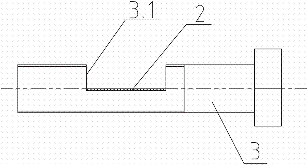
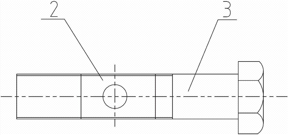
[0019] 1) First, the screw 3 with a total length of 100mm and a thread length of 30mm is processed with a square groove 3.1 at a distance of 20mm from the end of the thread to the end surface, and a reflective sheet 2 is attached to the square groove 3.1, such as image 3 As shown, the length of the square groove 3.1 is equal to the length of the reflector 2. The depth of the square groove 3.1 is the sum of half of the major diameter of the thread and the thickness of the reflector 2, so that the reflector 2 is attached to the outer surface of the reflector 2 with screws 3 on the center line, such as figure 2 Shown
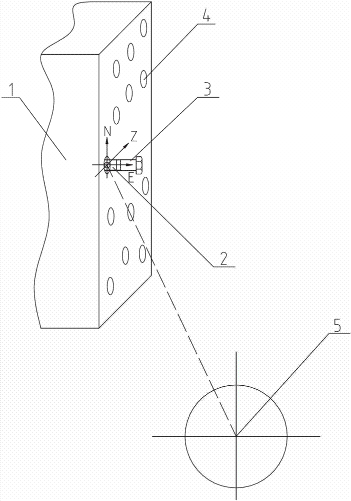
[0020] 2) Place the total station 5 on the ground which does not block the line of sight and has a firm foundation 5m outside the threaded hole system 1 under test, level the total station 5, and screw the screw 3 with a 20mm thread reserved Place the reflector 2 in the observable direction of the total station 5 in the threaded hole 4, such as figure 1 Shown
[0021...
Embodiment 2
[0024] 1) First, the screw 3 with a total length of 110mm and a thread length of 35mm is processed with a square groove 3.1 at a distance of 20mm from the end of the thread to the end surface, and a reflective sheet 2 is attached to the square groove 3.1, such as image 3 As shown, the length of the square groove 3.1 is equal to the length of the reflective sheet 2, and the depth of the square groove 3.1 is the sum of half the major diameter of the thread and the thickness of the reflective sheet 2, so that the outer surface of the reflective sheet 2 is screwed on the reflective sheet 2 3 on the center line, such as figure 2 Shown
[0025] 2) Place the total station 5 on the ground that does not block the line of sight 6m away from the threaded hole system 1 and has a firm foundation, level the total station 5, and screw the screw 3 with a 20mm thread reserved Place the reflector 2 in the observable direction of the total station 5 in the threaded hole 4, such as figure 1 Shown ...
PUM
 Abstract
Description
Claims
Application Information
 - R&D
- Intellectual Property
- Life Sciences
- Materials
- Tech Scout
- Unparalleled Data Quality
- Higher Quality Content
- 60% Fewer Hallucinations
Browse by: Latest US Patents, China's latest patents, Technical Efficacy Thesaurus, Application Domain, Technology Topic, Popular Technical Reports.
© 2025 PatSnap. All rights reserved.Legal|Privacy policy|Modern Slavery Act Transparency Statement|Sitemap|About US| Contact US: help@patsnap.com


