Controllers for power converters

A power converter and power control technology, applied in the direction of DC power input conversion to DC power output, output power conversion device, control/regulation system, etc., can solve the problem that the DC/DC converter 200 cannot reasonably control the output voltage, etc. question

Active Publication Date: 2013-01-16
AOTU ELECTRONICS WUHAN
View PDF4 Cites 4 Cited by
  • Summary
  • Abstract
  • Description
  • Claims
  • Application Information

AI Technical Summary

Problems solved by technology

Therefore, the DC / DC converter 200 cannot reasonably control the output voltage V OUT

Method used


Image

  • Controllers for power converters
  • Controllers for power converters
  • Controllers for power converters

Examples


Embodiment Construction

[0024]A detailed description will be given below of embodiments of the present invention. In the following detailed description of the invention, numerous specific details are set forth in order to provide a thorough understanding of the invention. However, it will be understood by those skilled in the art that the present invention may be practiced without these specific details. In other instances, well-known schemes, procedures, components and circuits are not described in detail in order to highlight the gist of the present invention.

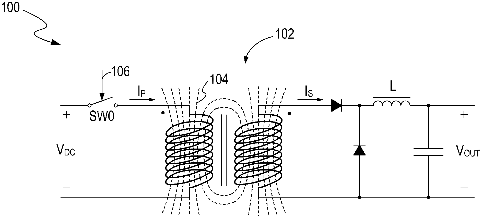
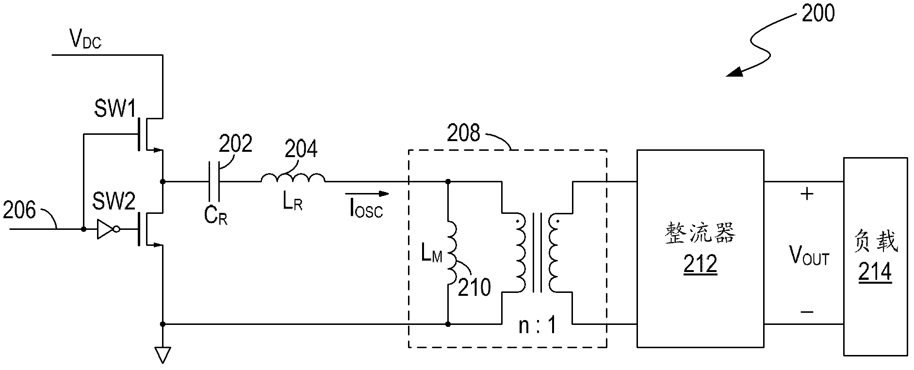
[0025] Embodiments of the present invention provide a controller and a power converter, such as a DC / DC converter. The present invention takes a DC / DC converter as an example to illustrate the specific implementation method. The controller controls the power conversion through the transformer circuit in the power converter. In one embodiment, the controller controls the current flowing through the primary coil of the transformer circuit,...


PUM


Abstract

In a controller for a power converter, a control terminal can provide a control signal to control a power converter. A cycle of the control signal includes a first time interval and a second time interval. The control circuitry can increase a primary current flowing through a primary winding of transformer circuitry and a secondary current flowing through a secondary winding of the transformer circuitry in the first time interval, and can terminate the increasing of the primary current in the second time interval. The control circuitry can also control the first time interval to be inversely proportional to an input voltage provided to the primary winding.

Description

technical field [0001] The invention relates to the field of power supply, in particular to a controller, a power converter and a method for controlling the power converter. Background technique [0002] figure 1 is a schematic circuit diagram of an existing DC / DC converter 100 . The DC / DC converter 100 includes a transformer 102 and a switch SW0 connected in series with the primary coil of the transformer 102 . The control signal 106 controls the output power of the DC / DC converter 100 by controlling the switch SW0. For example, the control signal 106 connects the primary winding of the transformer 102 to a power source, such as a DC voltage V DC , so that there will be a primary current I P flows through the primary winding of the transformer 102 . Correspondingly, the secondary current I S The current flows through the secondary coil of the transformer 102 and through the inductor L, and flows to the output terminal of the DC / DC converter 100 . At the same time, th...

Claims


Application Information

Patent Timeline
IPC IPC(8): H02M3/335
CPCH02M3/337Y02B70/126H02M3/33507H02M2001/0022H02M1/40H02M3/335H02M1/0022H02M3/28
Inventor 拉兹洛·利普赛依艾林·盖尔格斯库卡特林·波波维奇
Owner AOTU ELECTRONICS WUHAN
Why Eureka
Try Eureka