Method to prevent saturation in power amplifier control loop

Inactive Publication Date: 2005-09-22
PANASONIC CORP
View PDF5 Cites 28 Cited by
  • Summary
  • Abstract
  • Description
  • Claims
  • Application Information

AI Technical Summary

Benefits of technology

[0013] The present invention provides a solution to the deficiencies in the current art by providing a power control circuit that limits spurious outputs due to switching transients and / or over current conditions from occurring in the power amplifier section of GSM type transmitters. Spurious conditions occur when the control loop of the power amplifier of a transmitting device approaches saturation. The present invention operates to detect this condition and adjust the control loop of the power amplifier system to prevent it from entering saturation. The present invention detects the output of the power amplifier and converts the detected analog signal into a digital signal. The present invention then transforms the digital signal into the frequency domain. In one embodiment this is accomplished by using Fast Fourier Transform. The spectral characteristics of the signal are then analyzed to determine if the output level at various frequencies is approaching or exceeding threshold values. Such a condition indicates that the control loop of the power amplifier is approaching saturation. When this condition occurs, the present invention limits the output of the power amplifier by either reducing the supply voltage to the power amplifier or adjusting the bias voltage. Thus, the present invention provides a system and method to control the output of a power amplifier without the need for an isolator. The present invention can be implemented using discrete components or circuits or may be incorporated in a base band ASIC.

Problems solved by technology

Spurious conditions occur when the control loop of the power amplifier of a transmitting device approaches saturation.

Method used


Image

  • Method to prevent saturation in power amplifier control loop
  • Method to prevent saturation in power amplifier control loop
  • Method to prevent saturation in power amplifier control loop

Examples


Embodiment Construction

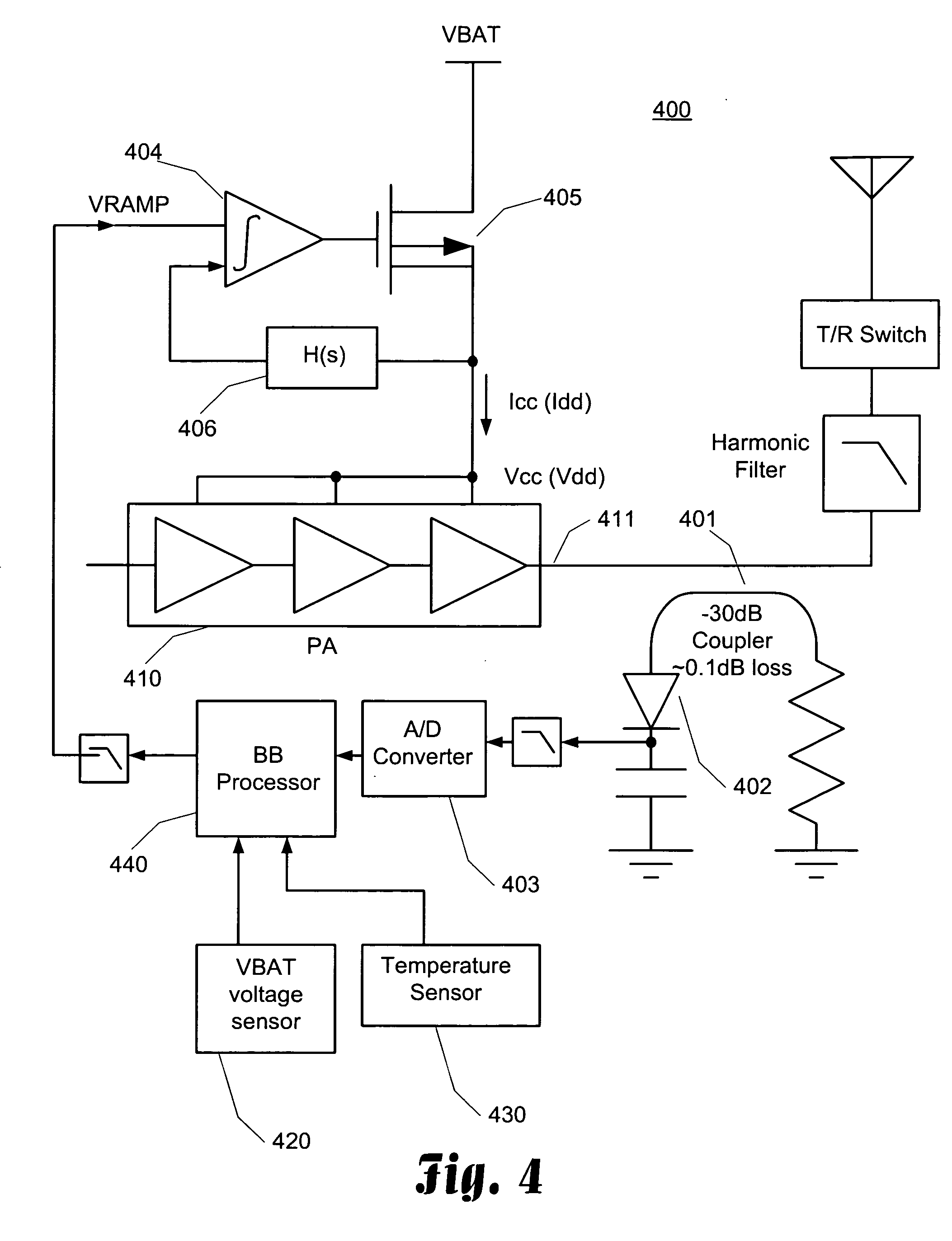
[0025] The present invention provides a power control circuit that limits spurious outputs due to switching transients and / or over current conditions by the power amplifier section of GSM type transmitters. In general, the present invention detects the output power envelop and performs an analog to digital conversion of the envelope. A processor than performs a Fast Fourier Transform on the digital signal to allow for an analysis of the spectrum characteristics of the signal. The amplitude of the detected spectrum can be analyzed at various critical frequencies to determine is the transmitted signal is within the parameters of the GSM specification. For instance, at 400 kHz, the GSM specification requires the amplitude of the signal to be below a particular threshold. When this threshold is exceeded, it is an indication that the spurious output caused by the switching transients may be violating the GSM specification. Although this technique does not directly detect over current con...


PUM


Abstract

When a power amplifier control loop operates near or in saturation, the quality of the output signal can be degraded and an over current condition can occur. To prevent this, the output signal of the power amplifier is detected, converted to digital, and then converted into the frequency spectrum by means of a Fast Fourier Transform. The spectral characteristics of the output signal are analyzed to determine if the power amplifier control loop is approaching or operating in saturation mode. This determination is made by looking at the power of the output signal at various frequencies. If the output at these frequencies exceeds a threshold value, the power amplifier control loop is approaching saturation. In this situation, the output of the power amplifier can be adjusted to prevent loop saturation. This can be accomplished by reducing the supply voltage to the power amplifier or adjusting the bias voltage.

Description

CROSS-REFERENCE TO RELATED APPLICATIONS [0001] This application is related to U.S. patent application Ser. No ______ entitled “METHOD TO CONTROL THE SUPPLY POWER BEING PROVIDED TO A POWER AMPLIFIER” filed on the same date as this application and commonly assigned to the assignee of this application, which application is incorporated herein by reference in its entirety.TECHNICAL FIELD [0002] The present invention is directed towards radio frequency transmission technology and, more specifically, towards a technique to detect and prevent saturation in a power amplifier control loop of a transmitter and thereby, reduce spurious outputs caused by loop saturation. BACKGROUND [0003] Cellular telephone technology has greatly advanced since its inception in the early 80's. Today, the Global System for Mobile communication (GSM) is one of the more prominent technologies being deployed in cellular systems throughout the world. GSM is a digital cellular communications system that was initially...

Claims


Application Information

Patent Timeline
Patent Type & Authority Applications(United States)
IPC IPC(8): H03G3/00H03G3/20H03G3/30
CPCH03F1/52H03G3/004H03G3/3047H03G2201/708H03G2201/206H03G2201/208H03G2201/307H03G2201/103
Inventor YAMAZAKI, RYONOELLERT, WILLIAM
Owner PANASONIC CORP
Why Eureka
Try Eureka