3D Object Detecting Apparatus and 3D Object Detecting Method

a technology of object detection and object position, applied in the field of three-dimensional (3d) object detecting apparatuses and 3d object detecting methods, can solve the problems of small areas of unnecessary portions that overlap the cuboid silhouette in the mask image, and achieve the effects of preventing user discomfort, improving and stabilizing the accuracy of detecting the position of 3d objects, and simple configuration

Active Publication Date: 2012-08-30
ALPINE ELECTRONICS INC
View PDF2 Cites 26 Cited by
  • Summary
  • Abstract
  • Description
  • Claims
  • Application Information

AI Technical Summary

Benefits of technology

[0027]In addition, when a warning is already output with respect to a 3D object determined not to be an approaching object on the basis of the difference area, the outputting of the warning is maintained. As a result, it is possible to prevent the user's discomfort due to sudden stopping of the warning ev

Problems solved by technology

On the other hand, since unnecessary portions other than the 3D object in the detection image often have a large share in the area of the detection image, the areas of the portions where such unnecessary portions overlap the cuboid silhouette in the mask imag

Method used


Image

  • 3D Object Detecting Apparatus and 3D Object Detecting Method
  • 3D Object Detecting Apparatus and 3D Object Detecting Method
  • 3D Object Detecting Apparatus and 3D Object Detecting Method

Examples


first embodiment

[0047]A first embodiment of a 3D-object detecting apparatus will be described below with reference to FIGS. 1 and 13.

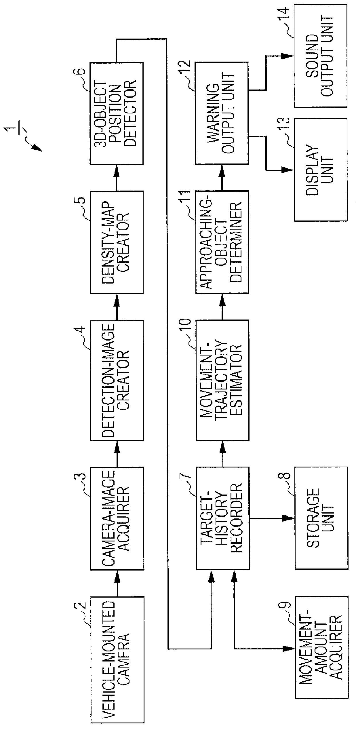
[0048]FIG. 1 is a block diagram illustrating a 3D-object detecting apparatus 1 mounted on a vehicle, which is a movable body. As illustrated in FIG. 1, the 3D-object detecting apparatus 1 has a vehicle-mounted camera 2, which serves as a single image-capture device. The vehicle-mounted camera 2 is mounted at a predetermined position of the vehicle.

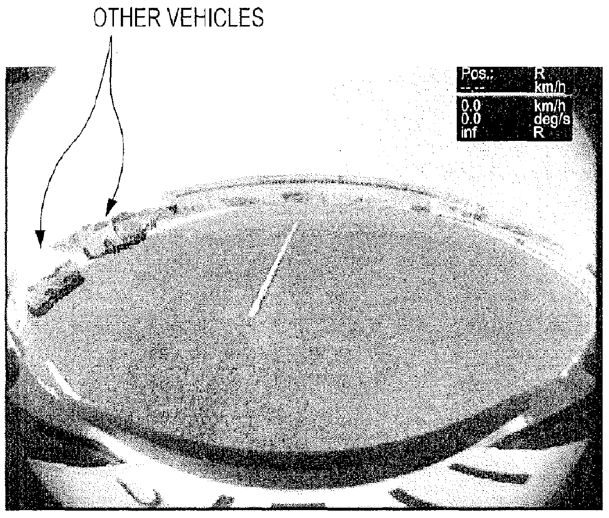
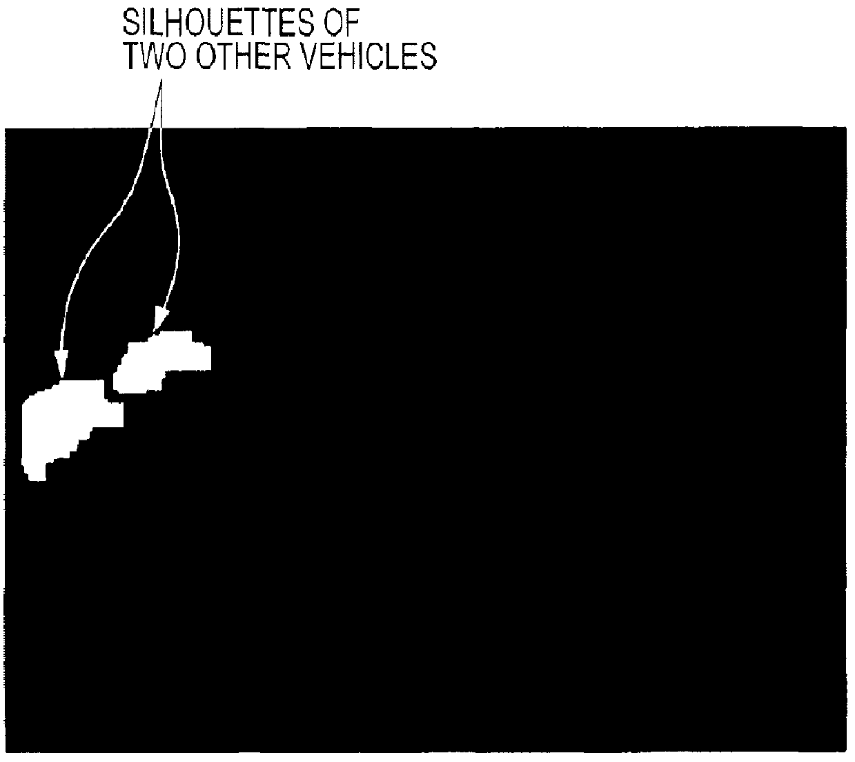
[0049]Upon being triggered by a user operation using an input device (e.g., an operation button, not illustrated), a predetermined drive operation of the vehicle, or the like, the vehicle-mounted camera 2 is adapted to capture an image of an image-capture region in the vehicle's surroundings (including a road surface, which is an image-capture surface) in a viewing angle at a predetermined frame rate. Examples of the “road surface” referred to herein include not only the road surface of a road, but also a pavement in a parki...

second embodiment

[0094]A second embodiment of the 3D-object detecting apparatus will be described below with reference to FIGS. 15 and 16. In the description below, elements whose basic configurations are substantially the same as or similar to those in the first embodiment are denoted by the same reference numerals.

[0095]FIG. 15 is a block diagram illustrating a 3D-object detecting apparatus 21 according to a second embodiment of the 3D-object detecting apparatus of the present invention. The 3D-object detecting apparatus 21 is mounted on a vehicle, as in the first embodiment.

[0096]As illustrated in FIG. 15, the 3D-object detecting apparatus 21 of the second embodiment has the same elements as those in the 3D-object detecting apparatus 1 of the first embodiment illustrated in FIG. 1. In addition to those elements in the first embodiment, as illustrated in FIG. 15, the 3D-object detecting apparatus 21 of the second embodiment further has a difference-area calculator 22, which serves as a difference-...


PUM


Abstract

A 3D-object detecting apparatus may include a detection-image creating device configured to detect a 3D object on an image-capture surface from an image captured by an image-capture device and to create a detection image in which a silhouette of only the 3D object is left; a density-map creating device configured to determine the 3D objects spatial densities at corresponding coordinate points in a coordinate plane on the basis of the detection image and mask images obtained for the corresponding coordinate points on the basis of virtual cuboids arranged for the corresponding coordinate points and to create a density map having pixels for the corresponding coordinate points such that the pixels have pixel values corresponding to the determined spatial densities; and a 3D-object position detecting device that detects the position of the 3D object as a representative point in a high-density region in the density map.

Description

RELATED APPLICATIONS[0001]The present application claims priority to Japanese Patent Application Serial Number 2011-038284, filed Feb. 24, 2011, the entirety of which is hereby incorporated by reference.BACKGROUND OF THE INVENTION[0002]1. Field of the Invention[0003]The present invention relates to three-dimensional (3D) object detecting apparatuses and 3D object detecting methods. In particular, the present invention relates to a 3D object detecting apparatus and a 3D object detecting method which are advantageous to detect a 3D object on an image-capture surface on the basis of an image captured by a single image-capture device.[0004]2. Description of the Related Art[0005]Hitherto, a traffic impediment warning system has been known. In some systems, an impediment on a road surface is detected in an image captured using a monoculiar (a single) camer mounted on a vehicle and the system issues a warning with respect to the detected impediment.[0006]Various 3D-object detecting methods...

Claims


Application Information

Patent Timeline
IPC IPC(8): G06K9/00
CPCG06T2207/30248G06T7/20
Inventor MORI, DAISHIMUNAKATA, KOUSUKEOBA, HIROKI
Owner ALPINE ELECTRONICS INC
Why Eureka
Try Eureka