Overall composite mechanical spiral type bulging device for car drive axle

A drive axle and helical technology, which is applied to the field of integral composite mechanical helical bulging devices for automobile drive axles, can solve the problems of difficult to control bulging force, high cost and high welding requirements, and achieve the effect of reducing space

Inactive Publication Date: 2013-01-23
CHONGQING UNIVERSITY OF SCIENCE AND TECHNOLOGY +1
View PDF8 Cites 26 Cited by
  • Summary
  • Abstract
  • Description
  • Claims
  • Application Information

AI Technical Summary

Problems solved by technology

[0006] Disadvantages: It is difficult to control the forming flow, prone to cracks and pores, and the weight is large, the subsequent processing is complicated, and the welding process is prone to cracks and deformation;
[0010] Disadvantages: There are many processes, which are only suitable for the production of axle housings with simple geometric shapes, and the strength of the produced axle housings is low, and the cost is high; in addition, there are high requirements for welding, quality is difficult to guarantee, and cracks, deformations, and leaks are prone to occur. Defects, and the welding zone is prone to fatigue fracture;
[0014] Disadvantages: horizontal cracks are prone to occur at the longitudinal slit, uneven width of the flanging at the pipa bag, and easy wrinkling and straining on the side;
[0018] Disadvantages: the bulging f

Method used


Image

  • Overall composite mechanical spiral type bulging device for car drive axle
  • Overall composite mechanical spiral type bulging device for car drive axle
  • Overall composite mechanical spiral type bulging device for car drive axle

Examples


no. 1 example

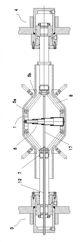
[0063] As shown in Figure 1, it is a structural schematic diagram of the first embodiment of the integral composite mechanical screw type bulging device of the automobile drive axle of the present invention after the workpiece bulging deformation is completed; Figure 2 is the integral composite mechanical spiral type of the automobile drive axle of this embodiment Schematic diagram of the structure of the bulging device before the bulging deformation of the workpiece.

[0064] The integral composite mechanical screw type bulging device of the automobile drive axle of the present embodiment includes a bulging inner mold 1, a bulging outer mold 2, and thrust hydraulic cylinders 3 and 3 which are respectively located at both ends of the bulging inner mold 1 and are used to provide bulging thrust. Thrust hydraulic cylinder 4.

[0065] As shown in Figure 4, the bulging inner mold 1 includes an upper module 1a and a lower module 1b respectively matched with the inner walls of the up...

no. 2 example

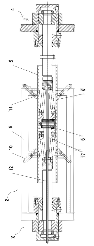
[0081] As shown in Figure 6, it is a structural schematic diagram of the second embodiment of the integral composite mechanical spiral bulging device of the automobile drive axle of the present invention after the workpiece bulging deformation is completed; Schematic diagram of the structure of the bulging device before the bulging deformation of the workpiece.

[0082] The bulging outer mold 2 of the present embodiment comprises an upper outer mold 13 and a lower outer mold 14, and the upper outer mold 13 and the lower outer mold 14 are respectively provided with an upper mold cavity having the same shape and structure as the outer walls of the upper and lower sides of the axle housing pipa bag 5a 13a and the lower mold cavity 14a, the support mechanism is the upper mold cavity support inner wall 13b and the lower mold cavity support inner wall 14b corresponding to the upper mold cavity 13a and the lower mold cavity 14a respectively with the transition surface 5b of the axle h...


PUM


Abstract

The invention relates to an overall composite mechanical spiral type bulging device for a car drive axle. The bulging device comprises a bulging inner die, a bulging outer die and two thrust hydraulic cylinders, wherein the bulging inner die comprises an upper die block and a lower die block, and an auxiliary pressure device is arranged between the upper die block and the lower die block. Two ends of the upper die block and the lower die block are respectively hinged with the piston rods of the two thrust hydraulic cylinders through link mechanisms. The link mechanisms comprise hinge mounts, and the hinge mounts are hinged with the upper die block and the lower die block through connecting rods. A spin screw mechanism is arranged between the two hinge mounts and comprises a screw, one end of the screw is installed on one hinge mount, and the other end of the screw is installed a spiral base arranged on the other hinge mount. The screw and the spiral base mutually rotate under the action of force, and the length of the screw is automatically regulated. The bulging outer die comprises a support mechanism positioned on the transitional surface of an axle shell pipa bag. The piston rods of the two thrust hydraulic cylinders are oppositely arranged, and a quick-detached connecting structure is arranged on the piston rod of one thrust hydraulic cylinder.

Description

technical field [0001] The invention belongs to the technical field of mechanical forming processing, in particular to an integral composite mechanical spiral bulging device of an automobile drive axle. Background technique [0002] The automobile manufacturing industry plays a pivotal role in my country's national economy. In recent years, my country's national economy has developed rapidly, and at the same time the automobile industry has also flourished. From the whole vehicle to the performance of the components, it has become the main subject of current industrial research, and the axle housing is one of the important parts of the automobile. The axle housing not only supports the automobile, but also serves as the differential and the final drive And the housing that drives the wheel drive. The quality of the automobile axle housing has a great influence on the performance of the vehicle. The axle housing not only needs to have sufficient strength, stiffness and fatig...

Claims


Application Information

Patent Timeline
IPC IPC(8): B21D53/88B21D37/10
Inventor 刘复元肖大志龚仕林徐明雷亚周雄林顺洪陈超欧忠文杨治明胡玉梅
Owner CHONGQING UNIVERSITY OF SCIENCE AND TECHNOLOGY
Why Eureka
Try Eureka