Yarn tension adjusting device of computer flat knitting machine

A technology for adjusting device and yarn tension, applied in knitting, weft knitting, textiles and papermaking, etc., can solve the problems of fabric pattern defects, broken yarn signal rods, i.e., weak force of conductor rods, and fabric scrapping, etc. quality effect

Inactive Publication Date: 2013-01-23
JIANGSU JINLONG TECHNOLOGY CO LTD
View PDF10 Cites 12 Cited by
  • Summary
  • Abstract
  • Description
  • Claims
  • Application Information

AI Technical Summary

Problems solved by technology

However, there are the following disadvantages: due to the relatively weak force of the broken yarn signal rod, that is, the force of the guide rod, there is a risk that the alarm will not be reported. Resulting in defective fabrics or even scrapping fabrics
For example, when weaving flower-shaped fabrics, different colors are served by different yarns. Once the yarn of a certain color is broken, the fabric pattern will be flawed.

Method used


Image

  • Yarn tension adjusting device of computer flat knitting machine
  • Yarn tension adjusting device of computer flat knitting machine

Examples


Embodiment Construction

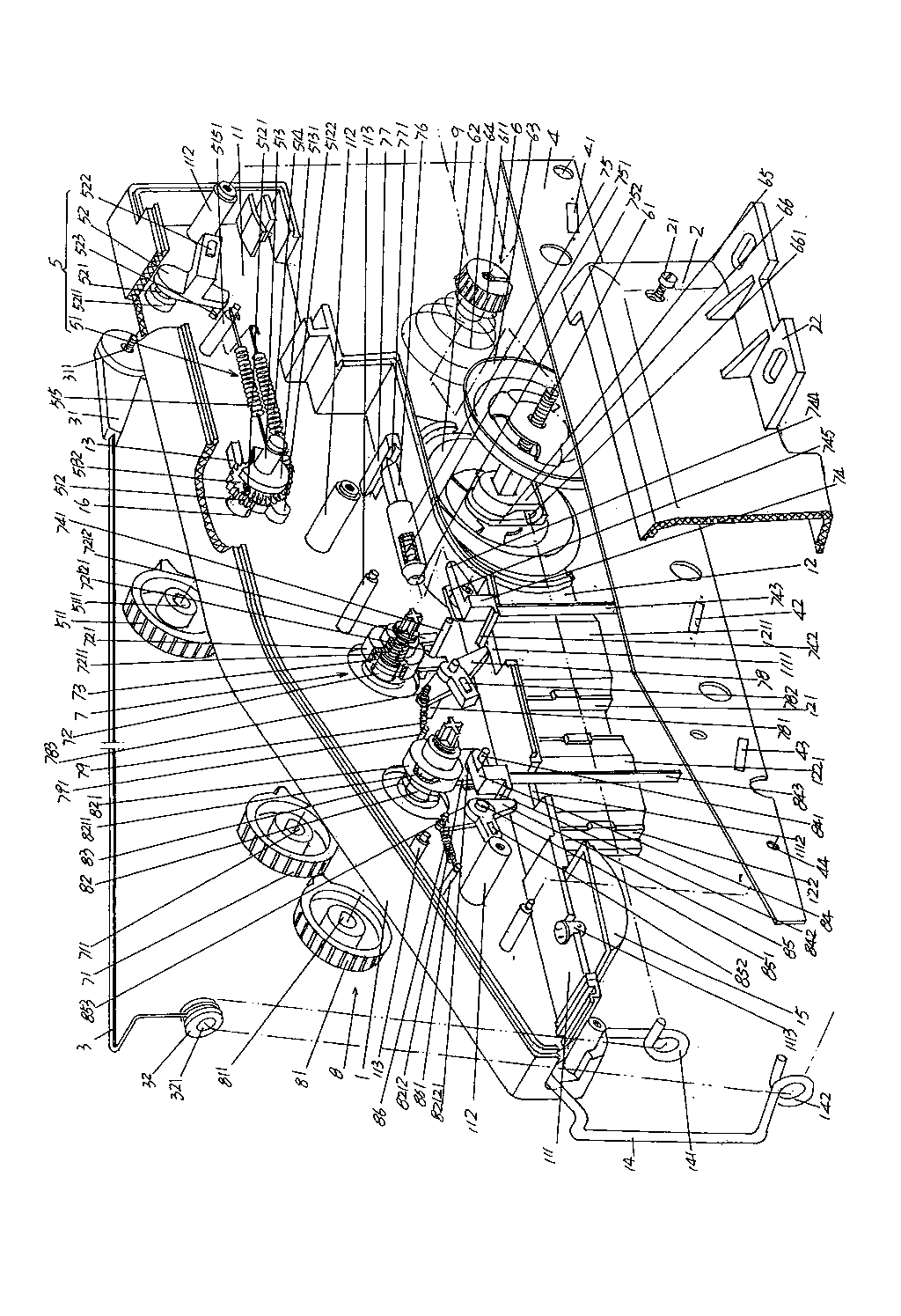
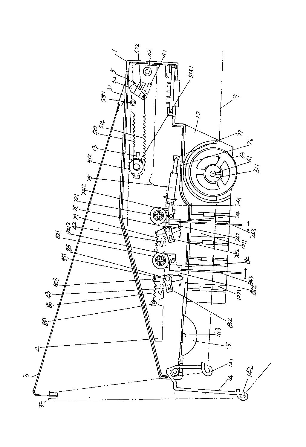
[0013] In order to enable the examiners of the patent office, especially the public, to understand the technical essence and beneficial effects of the present invention more clearly, the applicant will describe in detail the following in the form of examples, but none of the descriptions to the examples is an explanation of the solutions of the present invention. Any equivalent transformation made according to the concept of the present invention which is merely formal but not substantive shall be regarded as the scope of the technical solution of the present invention.

[0014] See figure 1 and figure 2 , before entering the description of the attached drawings, what the applicant needs to explain is: all concepts involving the orientation or directionality of left, center, right, up and down are aimed at the current figure 1 and figure 2 As far as the position state shown is concerned, it cannot and should not limit the protection scope of the technical solution...


PUM


Abstract

The invention relates to a yarn tension adjusting device of a computer flat knitting machine, belonging to the technical field of computer flat knitting machines. The yarn tension adjusting device comprises a box body, a box cover, a yarn guide rod, a circuit board, a broken yarn alarm mechanism and a yarn pretension adjusting mechanism, wherein a thread passing board extends from the box body, the yarn guide rod is arranged outside the box body, the right end of the yarn guide rod is fixed on a yarn guide rod seat, the left end of the yarn guide rod forms a free end, the circuit board is arranged in a box cavity and is electrically connected with a computer controller, the broken yarn alarm mechanism is connected with the yarn guide rod seat and is matched with the circuit board, and the yarn pretension adjusting mechanism is arranged on one side of the thread passing board and at the right end of a passing thread. The yarn tension adjusting device has the characteristics that the broken yarn alarm mechanism comprises a broken yarn signal rod applied force adjusting device and a broken yarn signal rod, the broken yarn signal rod applied force adjusting device is arranged on the box wall (of the box body) facing one side of the box cover and is also connected with the broken yarn signal rod, and the broken yarn signal rod is connected with the yarn guide rod seat and is also matched with the circuit board. The yarn tension adjusting device has the advantages that a signal can to be timely fed back to the circuit board when a yarn is broken so as to reflect the reliability of broken yarn alarm, thus guaranteeing the quality of braided fabric.

Description

technical field [0001] The invention belongs to the technical field of computerized flat knitting machines, in particular to a yarn tension adjusting device of a computerized flat knitting machine, which guides the yarn delivered by a yarn feeder to the computerized flat knitting machine under tension control. Machine head of knitting mechanism . Background technique [0002] The aforementioned yarn tension adjustment device is usually installed on the upper side of one end of the computerized flat knitting machine, so the industry vividly calls it a side antenna tension adjustment device, and even directly calls it a "side antenna platform". Since the tension of the yarn is not constant, because it is affected by its own material, that is, the fiber raw material that constitutes the yarn, and is also affected by the climate such as the ambient temperature and humidity, it is often necessary to adjust according to a certain or certain parameters during the weaving process...

Claims


Application Information

Patent Timeline
Patent Type & Authority Applications(China)
IPC IPC(8): D04B15/38D04B35/16
Inventor 金永良孙健兰先川石祖良
Owner JIANGSU JINLONG TECHNOLOGY CO LTD
Why Eureka
Try Eureka