Switching block and switching device comprising switching block

A switching device and switching device technology, applied in the direction of the parts of the flip switch/rocker switch, etc., can solve the problem that the handle cannot be attached to the mounting frame, etc.

Active Publication Date: 2013-01-23
PANASONIC INTELLECTUAL PROPERTY MANAGEMENT CO LTD
View PDF7 Cites 3 Cited by
  • Summary
  • Abstract
  • Description
  • Claims
  • Application Information

AI Technical Summary

Problems solved by technology

In other words, when the width dimension of the handle in the direction in which the mounting claws are a

Method used


Image

  • Switching block and switching device comprising switching block
  • Switching block and switching device comprising switching block
  • Switching block and switching device comprising switching block

Examples


Embodiment Construction

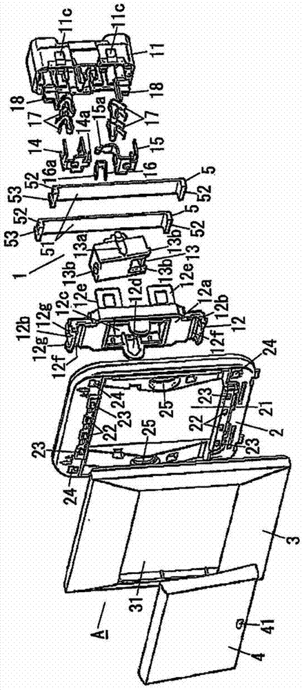
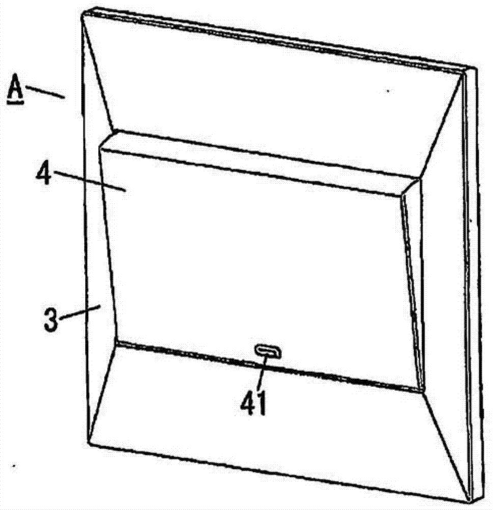
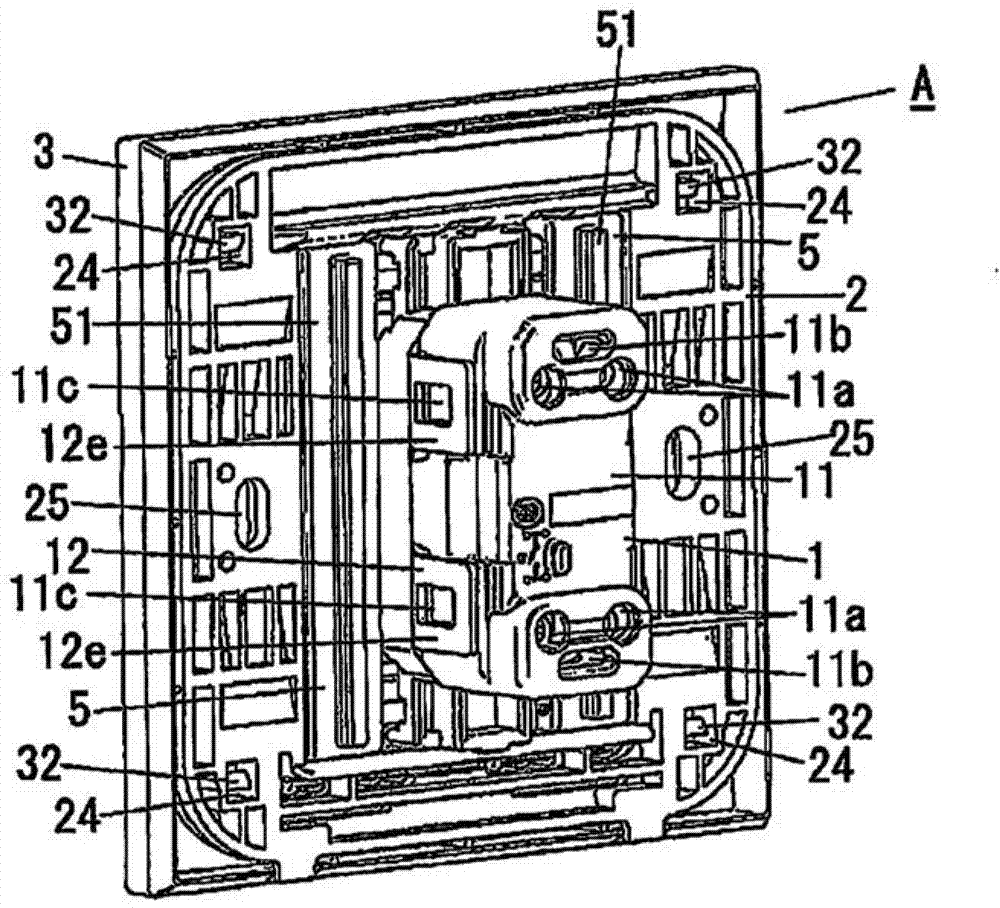
[0018] The following will refer to the attached Figure 1-5B A switching block and a switching device according to an embodiment of the present invention are described in detail. For example, the switch device of the present embodiment is embedded in an installation surface such as a wall surface, and is used as a changeover switch for turning on / off a light emitting device installed on a ceiling surface. Note that in the following descriptions, unless otherwise indicated, Figure 3B The up-down direction in is defined as the front-back direction, Figure 3B The right direction of is defined as the downward direction, and is the same as Figure 3B The direction perpendicular to the paper plane in is defined as the right-left direction.

[0019] figure 1 is an exploded perspective view showing the switchgear A of the present embodiment. The switch device A includes a switch device 1; a mounting frame 2 to which the switch device 1 is detachably attached from behind; a deco...


PUM


Abstract

The invention relates to a switching block and a switching device comprising the switching block, and specifically relates to a switching block (1) which can be detachably attached to a mounting frame used for wiring accessories. The switching block comprises a body (11) which is box shaped and has an opening on a front surface side; and a cover (12) which is attached to the body (11) to close the opening on the front surface side. A flipping component (13) for flipping internal contacts is arranged on a front surface of the cover (12). A handle (4) is detachably attached to the flipping component (13). Besides, the cover (12) has an attaching part (12b) for attaching the cover (12) to the mounting frame (2). The attaching part (12b) protrudes outwards over the body (11). According to the switching block (1), the handle (4) has a width larger than that of the body (11) and is attachable to the switching block (1).

Description

technical field [0001] The present invention relates to a switching (switching) device and a switching device including the switching device. Background technique [0002] Conventionally, there is provided a terminal device attached to a mounting frame for wiring accessories and embedded in a mounting surface (see, for example, Japanese Unexamined Patent Application Publication No. 2007-323936; Nos. [0020] to [0050] segment and figure 1 -4). A terminal assembly, such as a switchgear having a single-pole switching mechanism with single-pole / single-throw switching contacts (contacts), includes: a terminal block having quick-connect terminals for locking wires inserted through wire insertion holes; a body , for accommodating a switching device having movable and fixed contacts; and a cover, for covering the opening in the front surface of the body. [0003] A pair of mounting claws for attaching the terminal device to the mounting frame are respectively provided at both ends...

Claims


Application Information

Patent Timeline
IPC IPC(8): H01H23/04H01H23/02
Inventor 山口义男
Owner PANASONIC INTELLECTUAL PROPERTY MANAGEMENT CO LTD
Why Eureka
Try Eureka