Dilator and conveying mechanism thereof

A technology of conveying mechanism and dilator, applied in the field of medical devices, can solve the problems of blocking blood flow, prolonging operation time, patient danger, etc., and achieving the effect of stable expansion effect, convenient and simple conveying operation, and risk reduction.

Active Publication Date: 2015-01-07
张学民
View PDF6 Cites 0 Cited by
  • Summary
  • Abstract
  • Description
  • Claims
  • Application Information

AI Technical Summary

Problems solved by technology

[0003] The current way to dilate blood vessels is to fix the dilator on the wrinkled ball of a spherical catheter, and then insert the dilator and catheter together into the blood vessel. When the dilator reaches the specified position, the ball is expanded to achieve dilator expansion. However, in the above-mentioned embodiment, when the ball expands to expand the dilator, it also blocks the blood flow. Therefore, it is necessary to perform a blood pressure reduction operation before the operation, which not only prolongs the operation time but also reduces the blood pressure. Failure to press well can be dangerous to the patient

Method used


Image

  • Dilator and conveying mechanism thereof
  • Dilator and conveying mechanism thereof
  • Dilator and conveying mechanism thereof

Examples


Embodiment Construction

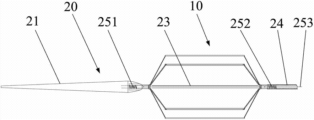
[0029] The present invention will be described in detail below in conjunction with the accompanying drawings. figure 1 It is a structural schematic diagram of the dilator and its delivery mechanism of the present invention. For ease of description, it is specified that the left side of the figure is the distal side of the dilator and its delivery mechanism, and the right side of the figure is the proximal side of the dilator and its delivery mechanism.

[0030] The delivery mechanism 20 includes a guide head 21, a middle tube 22, a core tube 23, an outer sheath tube 24, a loading mechanism 25 and a locking mechanism (not shown) arranged at the proximal end of the outer sheath tube 24, wherein the middle tube 22, the core tube 23 Both the outer sheath tube and the outer sheath tube 24 are hollow tubes, and the guide head 21 is conical, as the head end of the delivery mechanism 20 is convenient to move in the blood flow, and the guide head 21 is sheathed on the core tube 23 . I...


PUM


Abstract

The invention relates to a dilator and a conveying mechanism thereof, wherein the dilator is arranged on the conveying mechanism; the conveying mechanism comprises a leading head, a middle tube, a core tube and a sheath tube; the dilator is sleeved on the core tube and comprises a plurality of stripe supports; the conveying mechanism also comprises a loading mechanism; the loading mechanism loads the dilator, so that the dilator deforms to have a folding state and a dispersed dilating state; and in the dispersed dilating state, the supports of the dilator are in the shape of approximately more than half a ring extending outwards at the radial side of the core tube vertical to the blood flowing direction, and the dilator can be held in the sheath tube. According to the dilator and the conveying mechanism thereof, the dilator can dilate under the condition of not blocking the blood, thereby reducing the risk caused by blocking blood in operation; and simultaneously the dilator has different adjustable dilating degrees. In addition, the operation of conveying the dilator is more convenient and simpler.

Description

technical field [0001] The invention relates to a minimally invasive interventional medical device, in particular to a dilator for dilating blood vessels and a delivery mechanism thereof. Background technique [0002] The so-called dilator refers to a medical device placed there to maintain the size of the lumen to expand the stenosis or occlusion in order to treat various diseases caused by the stenosis or occlusion of blood vessels or other biological lumens. The dilator is delivered to the designated part of the blood vessel through the delivery mechanism to dilate the blood vessel. [0003] The current way to dilate blood vessels is to fix the dilator on the wrinkled ball of a spherical catheter, and then insert the dilator and catheter together into the blood vessel. When the dilator reaches the specified position, the ball is expanded to achieve dilator expansion. However, in the above-mentioned embodiment, when the ball expands to expand the dilator, it also blocks t...

Claims


Application Information

Patent Timeline
Patent Type & Authority Patents(China)
IPC IPC(8): A61F2/86A61F2/966
Inventor 张学民
Owner 张学民
Why Eureka
Try Eureka