Pay-off rack for electric power construction

A technology for power construction and pay-off racks, which is applied to overhead line/cable equipment, conveying filamentous materials, thin material processing, etc., can solve the problems of low applicability and practicability of pay-off racks for electric power construction, and achieve improvement Ease of use and practicability, the effect of improving the ease of use and improving applicability and practicability

Inactive Publication Date: 2021-01-01
于伟勇
View PDF8 Cites 0 Cited by
  • Summary
  • Abstract
  • Description
  • Claims
  • Application Information

AI Technical Summary

Problems solved by technology

[0007] The purpose of the present invention is to provide a pay-off frame for electric power construction, through the first threaded screw rod, the second threaded screw rod, the first limit rod, the second limit rod, the first limit seat and the second limit The design of the seat solves the problem of low applicability and practicability of the existing pay-off racks for electric power construction

Method used


Image

  • Pay-off rack for electric power construction
  • Pay-off rack for electric power construction
  • Pay-off rack for electric power construction

Examples


Embodiment Construction

[0038]The technical solutions in the embodiments of the present invention will be clearly and completely described below in conjunction with the accompanying drawings in the embodiments of the present invention. Obviously, the described embodiments are only a part of the embodiments of the present invention, rather than all the embodiments. Based on the embodiments of the present invention, all other embodiments obtained by those of ordinary skill in the art without creative work shall fall within the protection scope of the present invention.

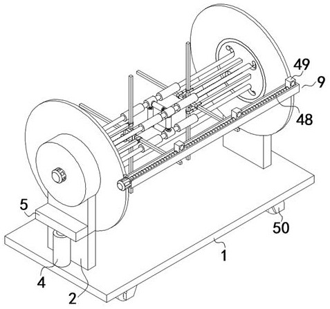
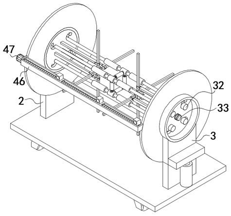
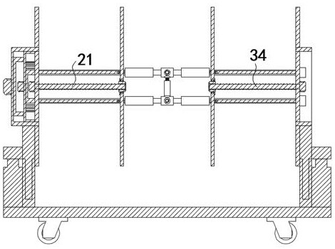
[0039]SeeFigure 1-10, The present invention is a pay-off rack for electric power construction, including a base 1, the upper surface of the base 1 is fixedly connected to two fixing plates 2; the inner walls of the two fixing plates 2 are slidably connected with a sliding plate 3; the upper surface of the base 1 And two drive push rods 4 are fixedly connected to the position of the fixed plate 2; the movable ends of the two drive push rods 4 ar...


PUM


Abstract

The invention discloses a pay-off rack for electric power construction, and relates to the technical field of electric power construction. The pay-off rack comprises a base, wherein the upper surfaceof the base is fixedly connected with two fixed plates; the inner walls of the two fixed plates are in sliding connection with sliding plates; the positions, which correspond to the fixed plates, of the upper surface of the base are fixedly connected with two drive pushing rods; the movable ends of the two drive pushing rods are fixedly connected with pushing bases; one surface of each of the twopushing bases is fixedly connected with the sliding plate on the corresponding position; one surface of one sliding plate is fixedly connected with a drive take-up and pay-off assembly; one surface ofthe other sliding plate is fixedly connected with a driven take-up and pay-off assembly; one surface of the drive take-up and pay-off assembly and one surface of the driven take-up and pay-off assembly are in sliding connection with a group of connecting base assemblies; and one surface of the drive take-up and pay-off assembly and one surface of the driven take-up and pay-off assembly are fixedly connected with a uniform wire arranging assembly. According to the pay-off rack disclosed by the invention, a first threaded lead screw, a second threaded lead screw, a first limiting base and a second limiting base are designed, so that the problem that an existing pay-off rack for electric power construction is low in applicability and practicability is solved.

Description

Technical field[0001]The invention belongs to the technical field of electric power construction, and particularly relates to a pay-off rack for electric power construction.Background technique[0002]Because of its easy conversion, transmission, and control, electric energy has gradually replaced steam power since the 1880s and has become the technological foundation of material and spiritual civilization in modern society. The transmission and distribution of electric energy is mainly realized through high and low voltage AC power networks. As the direction of the development of power transmission engineering technology, its focus is to study UHV (above 1 million volts) AC and DC transmission technologies to form a larger power network; at the same time, it is also necessary to study the technical issues of superconductor power transmission. The large-scale power system that emerged in the 20th century integrated power generation, transmission, transformation, distribution, and powe...

Claims


Application Information

Patent Timeline
Patent Type & Authority Applications(China)
IPC IPC(8): B65H49/30B65H57/28B65H67/02B65H49/34H02G1/02
CPCB65H49/30B65H57/28B65H67/02B65H49/34H02G1/02B65H2701/34
Inventor 於伟勇
Owner 于伟勇
Why Eureka
Try Eureka