Electric hub of electric sliding plate and wiring structure

A technology of electric wheel hub and wiring structure, which is applied in the direction of skateboards, ice skating, sports accessories, etc., can solve the problems that affect the overall flexibility and portability of electric skateboards, cannot use the way of outlet, and is not easy to protect the circuit system, etc., to save raw materials, The appearance is simple and beautiful, and the effect of simplifying the production process

Inactive Publication Date: 2014-07-02
朱凤春 +1
View PDF5 Cites 0 Cited by
  • Summary
  • Abstract
  • Description
  • Claims
  • Application Information

AI Technical Summary

Problems solved by technology

[0003]The electric skateboards that appear in the current market mostly use a single-layer board, and the circuit system is set at the bottom of the board, which is relatively large, and the road surface is uneven when the electric skateboard is running. Phenomenon, easy to appear bottoming phenomenon, not easy to protect the circuit system; electric skateboards use electric hubs, usually composed of brushless motors and hubs, the existing brushless motors and hubs are larger in size and higher in weight, which affects the overall flexibility of the electric skateboard lightness and portability
[0004] The motor wire of the brushless motor is usually led out from the motor shaft by a strand of wire harness. The electric wheel hub of the electric skateboard adopts an inner rotor brushless motor with two-way output shafts. The shell is fixedly connected, and the rotation of the motor shaft drives the hub shell to rotate; since the motor wire cannot pass through the high-speed rotating hub shell or the hub end cover, this way of outlet cannot be used

Method used


Image

  • Electric hub of electric sliding plate and wiring structure
  • Electric hub of electric sliding plate and wiring structure
  • Electric hub of electric sliding plate and wiring structure

Examples


Embodiment 1

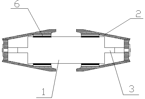
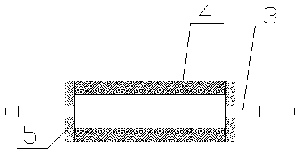
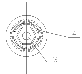
[0055] Embodiment 1: The motor 1 in the electric hub is a motor without a casing, the motor end cover 5 is directly arranged at both ends of the motor stator 4, the bearing 6 is arranged between the motor stator 4 and the hub shell 2, and the two shaft ends of the motor shaft 3 They are respectively fixedly connected with the end cover of the hub shell 2 at this end to form a rotational connection between the motor stator 4 and the hub shell 2; the motor end cover 5 is provided with an outlet hole 7 for the power supply line, and the outer periphery of the motor stator 4 is provided with an inner concave The wiring trough 8 passes through the bonding surface of the bearing 6 and the motor stator 4 along the 9 of the wiring trough.

[0056] More preferably, the wire outlet hole 7 is arranged at the contact section between the motor end cover 5 and the hub shell 2 , the wire outlet hole 7 communicates with the wiring groove 8 , and the motor wire passes through the wire outlet ho...

Embodiment 2

[0060] Embodiment 2: The wire outlet hole 7 is arranged at the installation place of the sub-beam 13 of the bracket of the motor stator 4 , and the motor wire is drawn out through the wire outlet hole 7 and then directly enters the bracket 11 .

[0061] When the installation space is sufficient, a motor casing 10 is arranged on the periphery of the motor stator 4, motor end covers 5 are arranged at both ends of the motor casing 10, a bearing 6 is arranged between the motor casing 10 and the hub casing 2, and the motor casing 10 and the hub casing 2 Rotational connection; the outlet hole 7 is set on the motor casing 10 .

Embodiment 3

[0062] Embodiment 3: The outlet hole 7 is set between the motor end cover 5 and the bearing 6, and the inner concave wiring groove 8 is opened on the outer periphery of the motor casing 10, and the wiring groove groove along the 9 passes through the attachment of the bearing 6 and the motor casing 10. meet face.


PUM


Abstract

The invention discloses a wiring structure of an electric hub of an electric sliding plate. A motor is an inner rotor brushless motor with output shafts in double directions; hub shells are symmetrically sleeved at the two ends of the motor respectively; and a motor shaft is fixedly connected with the hub shells. The electric hub is characterized in that: motor end covers are arranged at the two ends of a motor stator; a bearing is arranged between the motor stator and each hub shell; the motor end covers are provided with wire holes through which motor wires are led out; the motor stator is provided with a trough; the trough edge of the trough passes through a joint face between each bearing and the motor stator; a bracket main beam is rotationally and fixedly connected to a plate body bottom shell; a bracket auxiliary beam is fixedly connected with the motor; the bracket is provided with an internal routing channel; the inlet of the routing channel is communicated with a routing groove; the outlet of the routing channel is communicated with a thread hole in the plate body bottom shell; and motor wires pass out of the wire holes, pass through the routing groove and the bracket routing channel in sequence, and are inserted into a plate body through the thread hole. Due to the application of the electric hub, safe wire outlet and wiring of the electric hub of the electric sliding plate can be ensured, and the overall attractiveness of a vehicle can be improved.

Description

technical field [0001] The invention relates to the technical field of electric skateboards, in particular to a wiring structure of an electric hub of an electric skateboard. Background technique [0002] Electric skateboards are popular products nowadays. People's requirements for the shape and function of electric skateboards are constantly improving, and their performance and technical requirements are getting higher and higher. As a core component, the performance of electric hubs directly affects the operation of electric skateboards. [0003] The electric skateboards that appear in the current market mostly use a single-layer board surface, and the circuit system is set at the bottom of the board surface, which is relatively large. When the electric skateboard encounters uneven road surface during operation, it is easy to have a bottoming phenomenon and it is difficult to protect the circuit system; electric skateboards The electric wheel hub is usually composed of a b...

Claims


Application Information

Patent Timeline
Patent Type & Authority Patents(China)
IPC IPC(8): A63C17/12
Inventor 朱凤春其他发明人请求不公开姓名
Owner 朱凤春
Why Eureka
Try Eureka