
Floating breakwater structure

A wave breaker and floating technology, applied in the field of new floating wave breaker structures, can solve the problems of high cost, unsatisfactory wave breaking effect, unreasonable structural design, etc. The effect of increasing the number of construction work days

Active Publication Date: 2013-01-30
泉州龙闰海洋科技有限责任公司
View PDF5 Cites 7 Cited by
  • Summary
  • Abstract
  • Description
  • Claims
  • Application Information

AI Technical Summary

Problems solved by technology

However, due to the unreasonable structural design of the existing floating breakwater, the wave dissipation effect is not ideal, and the cost is still relatively high, so further improvement is still needed

Method used


Image

  • Floating breakwater structure
  • Floating breakwater structure
  • Floating breakwater structure

Examples


Embodiment Construction

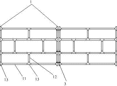
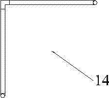
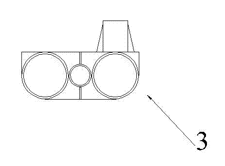
[0015] The present invention will be described in detail below in conjunction with accompanying drawing and specific embodiment: Figure 1 to Figure 4 Shown is a novel floating breakwater structure of the present invention, which is characterized in that it includes several unit grids 1, and the unit grids 1 include transverse pipes 11, longitudinal pipes 12 and tee pipes 13, and the transverse pipes 11 and longitudinal tubes 12 are evenly arranged and fixed to each other through the three-way tube 13 to form the above-mentioned unit grid 1, and the two rows of horizontal tubes 11 in the middle of the unit grid 1 are connected with several triangular brackets through the three-way tube 13 14. The two sides of the several triangular brackets 14 are laid with wave breaking nets 2; the horizontal pipes 11 or longitudinal pipes 12 at the boundary of the several unit grids 1 are flexibly connected by several double-ring sleeves 3. The unit grid 1 includes four rows of transverse tu...


PUM


Abstract

The invention discloses a floating breakwater structure which is characterized by comprising a plurality of grid units. Each grid unit comprises transverse pipes, longitudinal pipes and three-way pipes, the transverse pipes and the longitudinal pipes are arranged uniformly and are connected one another by the three-way pipes so that one grid unit is formed. A plurality of triangular supports are connected between two rows of transverse pipes in the middle of the grid units through the three-way pipes, and breakwater nets are laid on two sides of the triangular supports. The transverse pipes or the longitudinal pipes at the boundary of the grid units are movably connected by a plurality of double-ring sleeves. The floating breakwater structure has remarkable wave breaking effects, is low-cost relatively, convenient to demount, can drain water flow, has small affection to natural conditions of ports, and can be used for protecting fish culture and enhancement facilities and water areas such as artificial seawater baths, and accordingly double effects of saving investment and keeping good water quality exchange are achieved.

Description

technical field [0001] The invention relates to disaster prevention and mitigation equipment, in particular to a novel floating breakwater structure. Background technique [0002] The total area of ​​the global ocean is about 360 million square meters, accounting for 71% of the earth's surface area, and it is a huge treasure house of resources. In addition to abundant water resources and biological resources, offshore oil and other mineral resources are not only comparable to various resources on land, but also in huge quantities. In addition, marine space is also a resource with great potential. With the rapid development of human economic activities, land resources can no longer fully meet the needs of social development, and the role of ocean space will become more important. The ocean is becoming the second living space of human beings. At present, the development and utilization of the ocean by human beings will face an era of unprecedented rapid development. This ki...

Claims


Application Information

Patent Timeline
IPC IPC(8): E02B3/06
CPCE02B3/062Y02A10/11
Inventor 俞国耀刘庆安洪明全陈继梅
Owner 泉州龙闰海洋科技有限责任公司
Learn More