
Filter device of transmission system

A technology of transmission system and filtering device, which is applied in the directions of transmission parts, dispersed particle filtration, gear lubrication/cooling, etc. It can solve the problems of reduction of turns, wear of the transmission group 132, loosening and falling of the screw 101, etc., and achieve a combination of lifting force, improve stability, and prevent loosening and falling

Inactive Publication Date: 2013-01-30
KYMCO
View PDF8 Cites 4 Cited by
  • Summary
  • Abstract
  • Description
  • Claims
  • Application Information

AI Technical Summary

Problems solved by technology

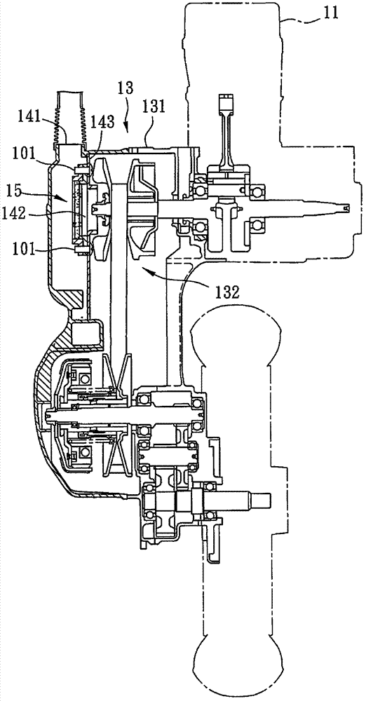
[0007] Generally speaking, in order to reduce the impact of the filter device 15 on the air intake of the air inlet 141, the skeleton of the filter device 15 is generally made of plastic material, or in order to avoid interference and the transmission device 13 is often designed to be larger. Thin, because the skeleton of this filtering device 15 is mostly made of plastic material, therefore, intensity is relatively poor, easy to loosen or even damage after dismounting for many times, and then affects the filtering effect of this filtering device 15; Because the skeleton thickness of the filter device 15 is relatively thin, the number of turns that can be locked by the screw 101 is reduced, which affects the bonding force between the filter device 15 and the wind deflector 143, making it possible for the screw 101 to Due to the vibration of the vehicle, it is loose and dropped, or even falls into the transmission box 131, which will cause wear or even damage to the transmission group 132

Method used


Image

  • Filter device of transmission system
  • Filter device of transmission system
  • Filter device of transmission system

Examples


Embodiment Construction

[0049] The aforementioned and other technical contents, features and effects of the present invention will be clearly presented in the following detailed description of three preferred embodiments with reference to the drawings.

[0050] Before the present invention is described in detail, it should be noted that in the following description, similar elements are denoted by the same reference numerals.

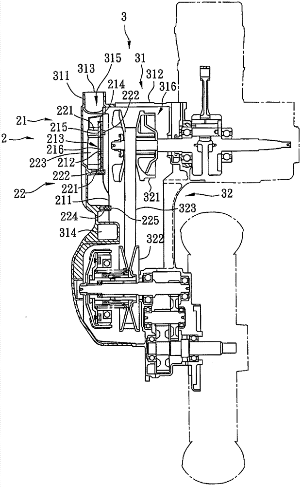
[0051] refer to image 3 , the first preferred embodiment of the filter device 2 of the transmission system of the present invention is suitable for a transmission system 3 of a motorcycle. The transmission system 3 includes a transmission box 31 and a transmission mechanism 32 accommodated in the transmission box 31. The transmission box 31 forms an air inlet 313 capable of sucking in air and an air outlet 314 capable of discharging air.

[0052] The transmission mechanism 32 has a driving disk 321 disposed in the transmission box 31 , a passive disk 322 spaced apart from th...


PUM


Abstract

The invention discloses a filter device of a transmission system. The drive system comprises a transmission case and a transmission mechanism, wherein the filter device comprises a filter unit and a connection unit. The filter unit comprises a partition plate and a filter mechanism, wherein the partition plate is arranged in the transmission case and is provided with an opening, and the filter mechanism is arranged on the partition plate and covers the opening. The connection unit comprises a plurality of connection columns and a plurality of connection parts which can connect the filter mechanism and the partition plate with each connection column. Through utilizing the connection columns and the connection parts which can correspondingly connect the filter mechanism and the partition plate with each connection column, the capability of the connection parts for connecting the filter mechanism and the partition plate is effectively improved, the connection parts can also be prevented from being vibrated to loosen and fall off, and furthermore, the stability of the filter unit is improved.

Description

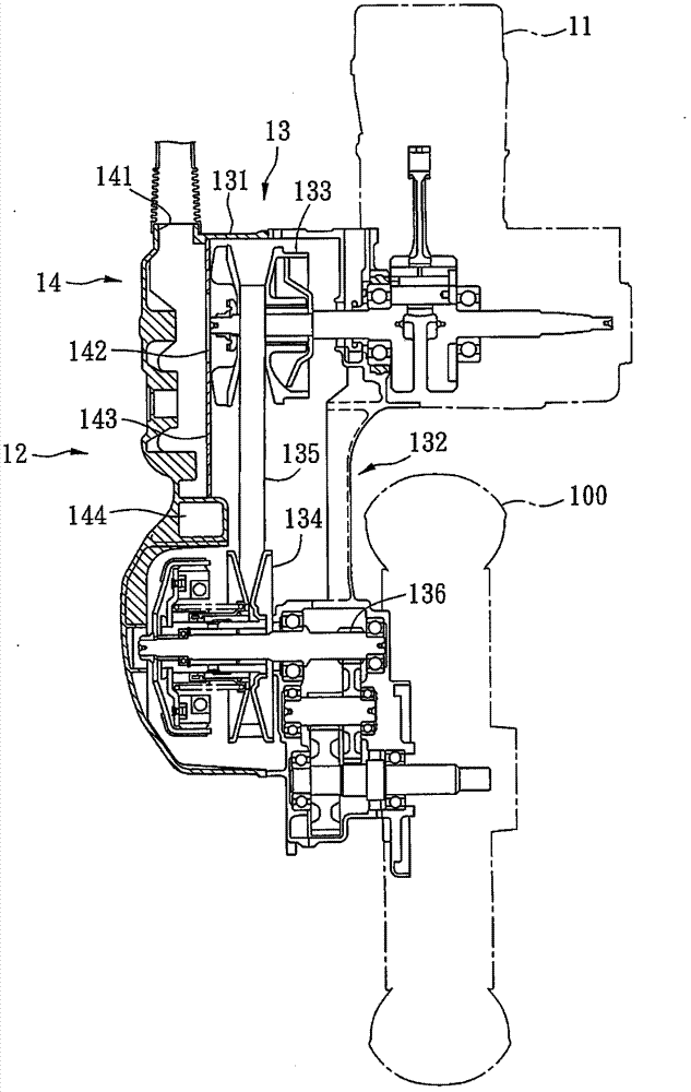
【Technical field】 [0001] The invention relates to a filtering device, in particular to a filtering device of a transmission system. 【Background technique】 [0002] refer to figure 1 , the existing scooter motorcycle is to input the oil gas mixed with air and fuel oil into an engine 11 to ignite and explode to generate power, and then utilizes a transmission system 12 to drive a wheel 100 by transmitting power. The transmission system 12 includes a transmission device 13 for transmitting the power of the engine 11 , and a cooling device 14 for cooling the transmission device 13 . [0003] The transmission device 13 has a transmission box 131 , and a transmission set 132 disposed in the transmission box 131 to transmit the power generated by the engine 11 to the wheels 100 . The shifting group 132 includes a drive pulley 133 driven by the engine 11, a passive pulley 134 spaced apart from the drive pulley 133, a belt 135 covering the drive pulley 133 and the drive pulley 134,...

Claims


Application Information

Patent Timeline
IPC IPC(8): F16H57/04F16H57/027B01D46/00
Inventor 李俊敬巫善睿范栩
Owner KYMCO
Learn More