
Coupling device

A coupling device and coupler technology, applied in the direction of connecting devices, electrical components, circuits, etc., can solve problems such as reducing system stability, increasing the difficulty of reconstruction, increasing the number of connectors between couplers and external new devices, and potential failure points. , to achieve the effect of improving stability

Active Publication Date: 2015-05-20
CHINA UNITED NETWORK COMM GRP CO LTD
View PDF4 Cites 0 Cited by
  • Summary
  • Abstract
  • Description
  • Claims
  • Application Information

AI Technical Summary

Problems solved by technology

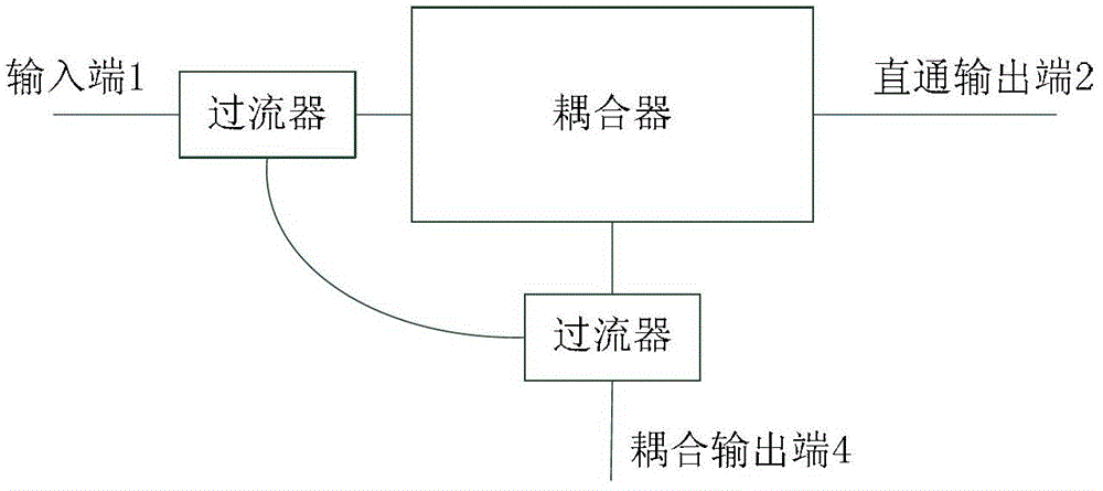
[0004] In the process of realizing the above-mentioned prior art, the inventor found that there are at least the following technical problems in the prior art: the newly added device not only needs to be re-laid, which increases the difficulty of transformation, but also increases the number of joints between the coupler and the externally added device and potential failure points, thereby reducing system stability and increasing system transformation costs

Method used


Image

  • Coupling device
  • Coupling device
  • Coupling device

Examples


Embodiment Construction

[0013] In order to make the purpose, technical solutions and advantages of the embodiments of the present invention clearer, the technical solutions in the embodiments of the present invention will be clearly and completely described below in conjunction with the drawings in the embodiments of the present invention. Obviously, the described embodiments It is a part of embodiments of the present invention, but not all embodiments.

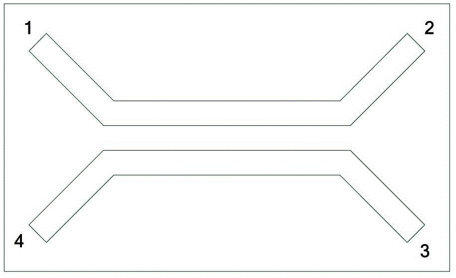
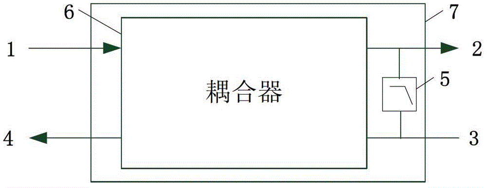
[0014] image 3 It is a structural schematic diagram of Embodiment 1 of the coupling device in the present invention, such as image 3 As shown, the coupling device 7 may include the above-mentioned figure 1 The shown coupler 6 and filter circuit 5 having a microstrip line structure, the coupler 6 includes an input terminal 1, a through output terminal 2, an isolation terminal 3 and a coupled output terminal 4, and the filter circuit 5 is connected in series Between the through output terminal 2 of the coupler 6 and the isolation terminal 3, so th...


PUM


Abstract

The invention provides a coupling device. The coupling device comprises a coupler and a filter circuit; the coupler is provided with a microstrip line structure; the coupler comprises an input end, a through output end, a separating end and a coupling output end; the filter circuit is connected in series between the through output end and the separating end of the coupler, so that the current inflowing from the input end of the coupler can pass through the through output end, then is transmitted to the separating end by the filter circuit, and is finally output by the coupling output end. According to the coupling device, the filter circuit is added between the through output end and the separating end, so that low-frequency current can pass through the coupling device; the output of the through output end and the output of the coupling output end respectively provide power to remote end nodes, and no influence is brought to the coupling of radio frequency signals between parallel coupling seams, so that the functions of transmitting the current by the coupling device can be achieved, and the amount of the joints of the coupling device and external devices is unchanged, and as a result, the stability of the system can be improved.

Description

technical field [0001] The invention relates to the co-cable transmission technology, in particular to a coupling device. Background technique [0002] Co-cable transmission technology is a radio frequency broadband technology. It transmits the video, audio or data baseband signals that need to be transmitted on the high-frequency carrier. After reaching the destination, the baseband signal is separated from the carrier. Since the frequency bandwidth of the RF coaxial cable can reach more than 0-3GHz, while the frequency of direct current is 0Hz and the frequency of alternating current is 50Hz, both direct current and alternating current can also be transmitted through the coaxial cable. For example, at the input end, a power supply can be used The interposer (or remote power supply unit) completes the mixing of power supply and high-frequency carrier, provides a high-frequency channel and isolates the signal channel of high-frequency and power supply. After the signal reac...

Claims


Application Information

Patent Timeline
Patent Type & Authority Patents(China)
IPC IPC(8): H01P5/16
Inventor 吕召彪李新中杨军马彰超王友祥范斌王健全
Owner CHINA UNITED NETWORK COMM GRP CO LTD
Learn More