Supercharge Your Innovation With Domain-Expert AI Agents!

Wire terminal structure and manufacturing method thereof

A wire terminal and manufacturing method technology, applied in the field of wire terminal structure, can solve the problems of unfavorable long-term use, unsatisfactory plating conductivity, low hardness, etc., and achieve the effect of not being easily deformed

Active Publication Date: 2016-04-06
SWITCHLAB SHANGHAI
View PDF7 Cites 0 Cited by
  • Summary
  • Abstract
  • Description
  • Claims
  • Application Information

AI Technical Summary

Problems solved by technology

However, the conductive effect of this coating is still not ideal, which is not conducive to long-term use.
[0005] If a material with better conductivity (for example, red copper material) is selected to manufacture or integrally form the body and the conductive rod; and because of the low hardness of the material, the terminal device is easily deformed; and this situation is not what we expect

Method used


Image

  • Wire terminal structure and manufacturing method thereof
  • Wire terminal structure and manufacturing method thereof
  • Wire terminal structure and manufacturing method thereof

Examples


Embodiment Construction

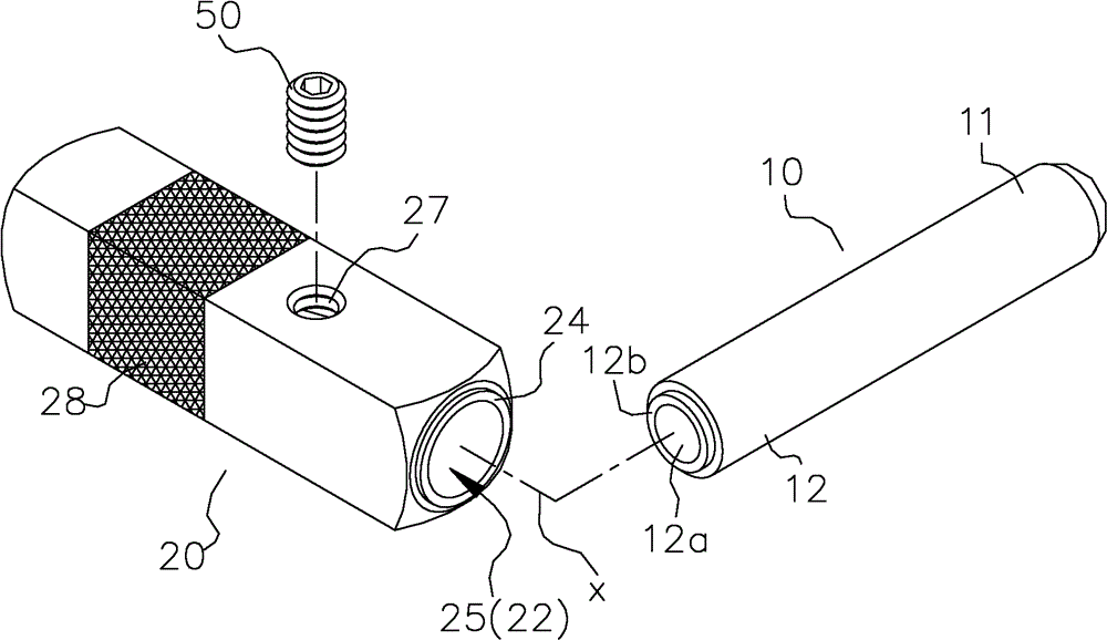
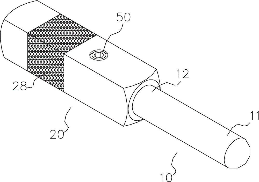
[0067] like figure 1 , figure 2 As shown, the wire terminal structure of the present invention includes: a conductor 10 and a seat 20. The conductor 10 selects a material with better conductivity (for example, red copper or similar materials) to form a column or rod structure type of. The conductor 10 has a first end 11 and a second end 12 . The first end 11 is used to insert the signal end or the power end of the electronic product; the second end 12 includes a cavity 12a for pivoting a (ground) wire to form a ground wire mechanism.

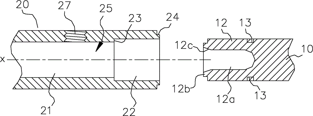
[0068] like image 3 , Figure 4 As shown, corresponding to the conductor 10 , the seat 20 defines a cavity 25 in the direction of the axis x; the cavity 25 includes a first area 21 and a second area 22 . The second area 22 is used to combine the second end 12 of the conductor 10 ; the inner diameter of the second area 22 of the chamber is larger than that of the first area 21 ; a neck 23 is formed between the second area 22 and the first ...


PUM


Abstract

The invention discloses a lead wire terminal structure comprising a conduction body and a base. The conduction body is provided with a first end and a second end; the base is provided with an axis and a cavity located on the axis; and the cavity is provided with a first area and a second area for combining a second area of the second end of the conduction body. A partial material or a local area of the base is clamped with the conduction body through punching operation, so that the base and the conduction body can be an entire state. The invention further discloses a manufacturing method of the lead wire terminal structure. The lead wire terminal structure provided by the invention has the advantage of difficulty of deformation under the condition of relatively good conduction efficiency.

Description

technical field [0001] The invention relates to a wire terminal structure, in particular to a terminal structure for wire insertion and connection. The invention also relates to a manufacturing method of the terminal structure. Background technique [0002] Use wire terminal devices to connect the signal terminal and power terminal of electronic products to output signals of electronic products, or establish a good grounding grounding device to shield electromagnetic wave interference, maintain input voltage, reduce noise accumulation, improve electrical performance or avoid equipment accidents damage, such as electric shock, fire, etc. Generally, this type of wire terminal device is integrally formed, including: a conductive rod (or electrode connector) and a main body (or base body). The body contains a shaft hole, so that the ground wire enters the body and connects with the conductive rod to establish a wire connection. [0003] In order to avoid the easy deformation ...

Claims


Application Information

Patent Timeline
Patent Type & Authority Patents(China)
IPC IPC(8): H01R4/18H01R43/16H01R13/02
Inventor 徐文斌吴智远
Owner SWITCHLAB SHANGHAI
Features
  • R&D
  • Intellectual Property
  • Life Sciences
  • Materials
  • Tech Scout
  • Unparalleled Data Quality
  • Higher Quality Content
  • 60% Fewer Hallucinations
Learn More