Suction catheter

A technology for suction tubes and catheters, which is applied in the direction of catheters, etc., can solve the problems of reduced passage area and reduced suction performance, and achieve the effects of suppressing the reduction of suction performance, suppressing the reduction of suction performance, and suppressing the reduction of insertion performance

Active Publication Date: 2013-02-06
GOODMAN & COMPANY
View PDF1 Cites 3 Cited by
  • Summary
  • Abstract
  • Description
  • Claims
  • Application Information

AI Technical Summary

Problems solved by technology

However, at this time, since the passage area of ​​the suction lumen is reduced by the guide wire tube, the suction performance may decrease

Method used


Image

  • Suction catheter
  • Suction catheter
  • Suction catheter

Examples


Embodiment Construction

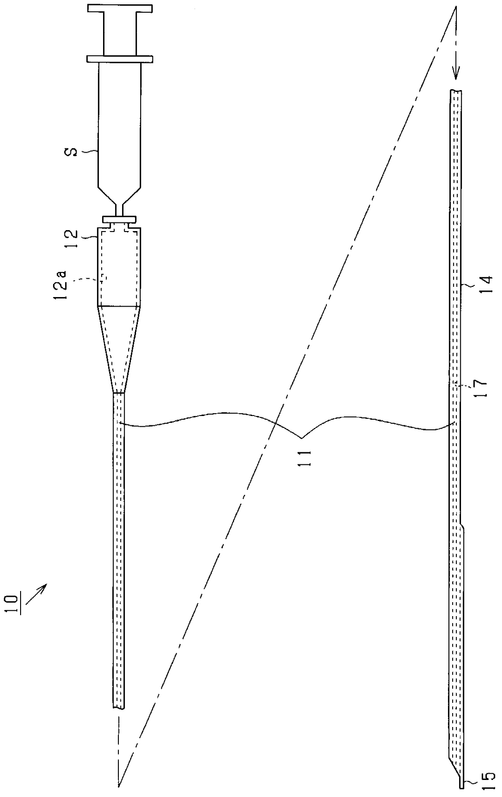
[0042] Hereinafter, an embodiment in which the present invention is embodied will be described with reference to the drawings. In this embodiment, a suction catheter for sucking thrombus is embodied. figure 1 It is a schematic overall side view showing the structure of the suction catheter.

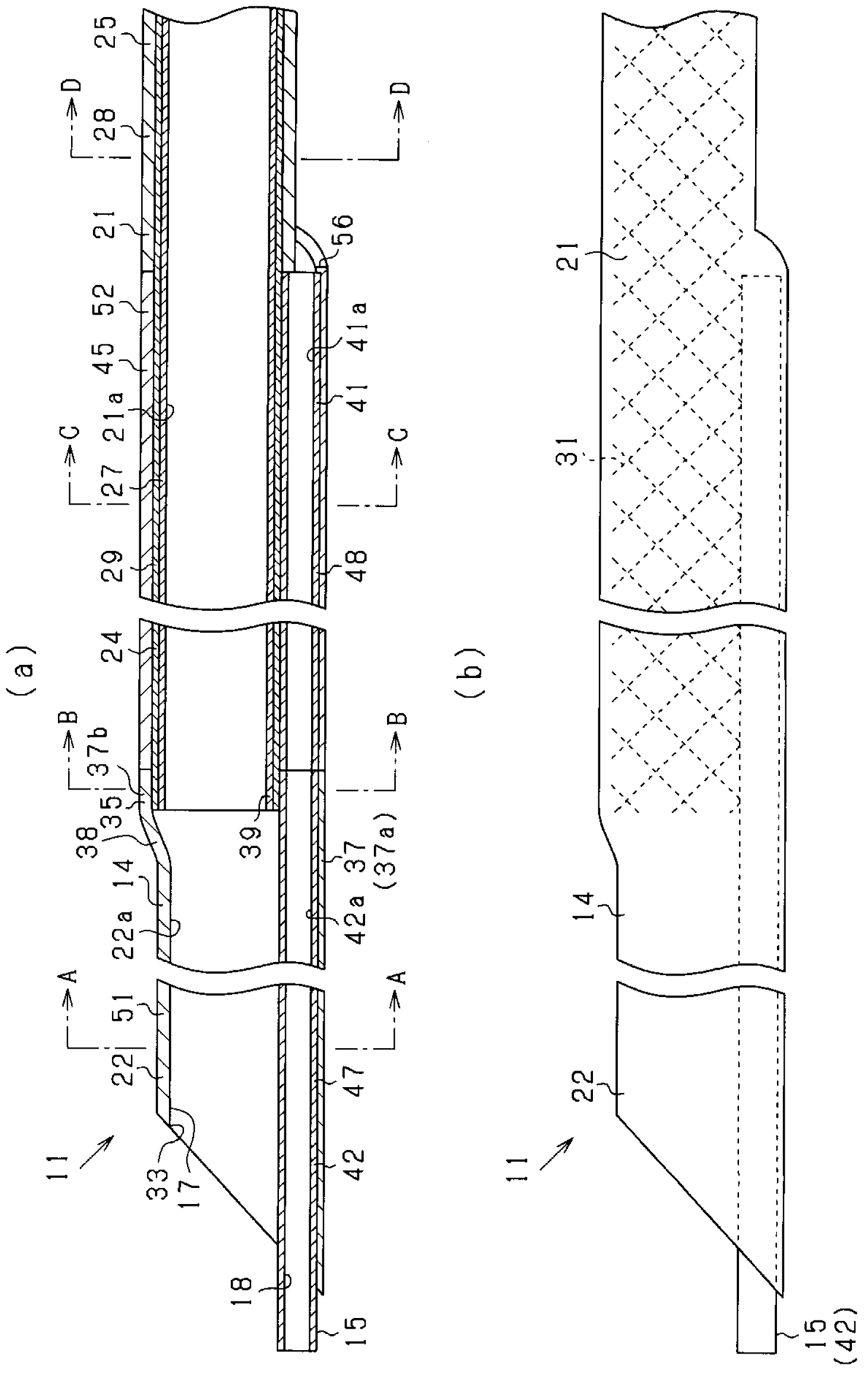
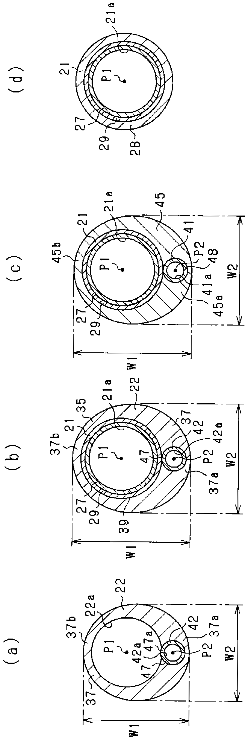
[0043] Such as figure 1 As shown, the suction catheter 10 is formed to have a length of 1 m to 2 m, and includes a catheter body 11 and a cannula 12 attached to the proximal end (base end) of the catheter body 11 . The catheter main body 11 includes a suction tube 14 and a wire guide tube 15 provided on the distal end side of the suction tube 14, and the respective tubes 14, 15 are formed by fusion bonding. The suction tube 14 has a suction lumen 17 inside it, and the guide wire tube 15 has a guide wire lumen 18 (referring to figure 2 and image 3 ).

[0044] The cannula 12 has a fluid passage 12a inside it that communicates with the suction lumen 17 of the suction tube 14 . A syring...


PUM


Abstract

The present invention provides a suction catheter which inhibits the decrease of internal insertion and decrease of suction performance. The suction catheter includes a catheter body (11) and a casing pipe. The catheter body (11) comprises: a suction pipe (14) having a suction pipe cavity (17) for sucking foreign bodies; and a wire guide pipe (15) having a wire guide pipe cavity (18) for the guide wire to pass through. In addition, the catheter body (11) has a distal-side pipe (51) and a proximal-side pipe (52). In the distal-side pipe (51), a pipe cavity separation part for separating the suction pipe cavity (17) and the wire guide pipe cavity (18) is protruded towards the central portion of the suction pipe cavity (17). In the proximal-side pipe (52), the pipe cavity separation part is protruded back to the central portion of the suction pipe cavity (17).

Description

technical field [0001] The present invention relates to a suction catheter for removing thrombus and other foreign bodies in the blood vessel. Background technique [0002] Conventionally, a suction catheter for suctioning and removing a foreign body such as a thrombus present in a blood vessel is known (for example, refer to Patent Document 1). The suction catheter includes a suction tube inside which has a suction lumen for suctioning foreign matter. Using this suction catheter, for example, when suctioning a thrombus in a blood vessel, first, the treatment agent inserts the suction catheter into the blood vessel and moves it so that the suction port formed at the distal end of the suction tube reaches the treatment target site where the thrombus exists. . Then, the suction lumen is negative-pressured using a suction tool attached to the proximal end of the suction tube, thereby suctioning and removing the thrombus through the lumen. [0003] It should be noted that, wh...

Claims


Application Information

Patent Timeline
IPC IPC(8): A61M25/00
Inventor 嘉手苅博日和秀人长岛义昭井泽圭
Owner GOODMAN & COMPANY
Why Eureka
Try Eureka