Control cable installation structure

A technology of installation structure and cables, applied in the direction of linear motion shaft, flexible shaft, shaft, etc., can solve the problem of inclination of the installation part, achieve the effect of preventing falling off and simplifying the structure

Active Publication Date: 2015-11-25
HONDA MOTOR CO LTD
View PDF10 Cites 0 Cited by
  • Summary
  • Abstract
  • Description
  • Claims
  • Application Information

AI Technical Summary

Problems solved by technology

[0009] However, when a load is applied to the part separated from the mounting part, the mounting part will tilt

Method used


Image

  • Control cable installation structure
  • Control cable installation structure
  • Control cable installation structure

Examples


Embodiment

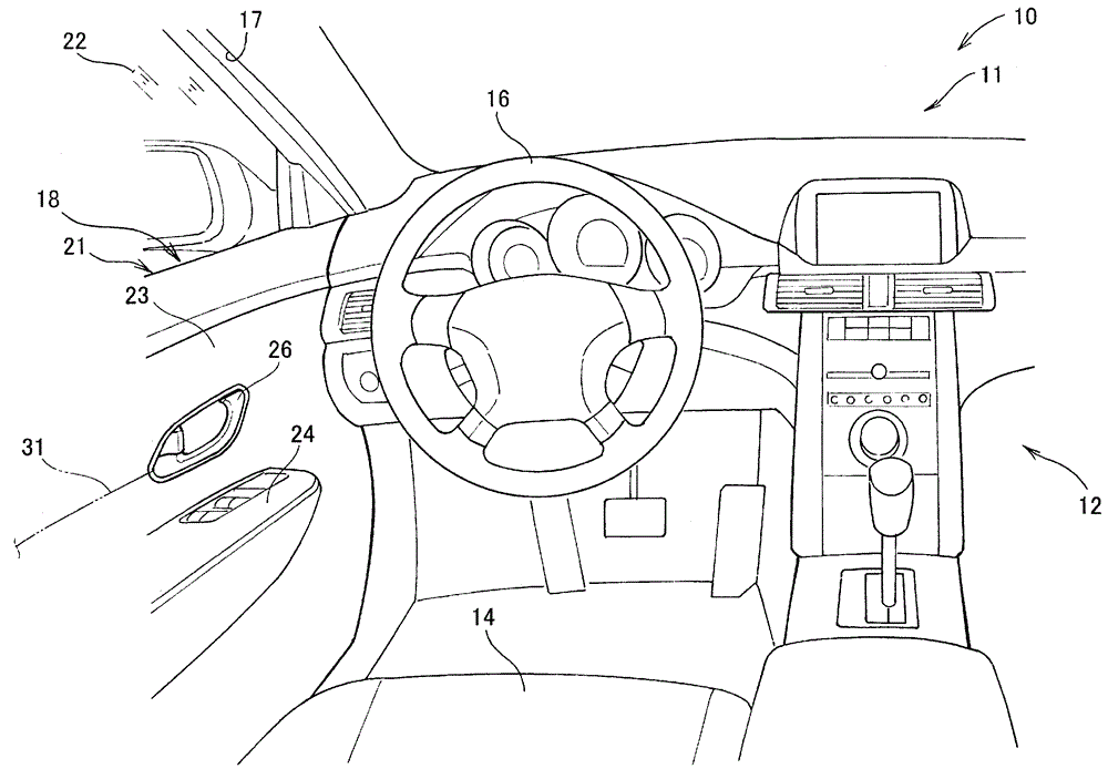
[0046] Such as figure 1 and figure 2 As shown, the vehicle 10 includes a driver's seat 14 arranged in the cabin 12 for the driver to sit on, a steering wheel 16 for manipulating the front wheels (not shown), a door opening 17 outside the driver's seat 14 for the driver to get on and off, A vehicle door 18 covering the door opening 17 in an openable and closable manner and a striker 19 provided on the door opening 17 and locking the door 18 are provided.

[0047] The door 18 has a door main body 21 mounted on the vehicle body 11 to be able to open and close, a door glass 22 mounted on the door main body 21 to be able to move up and down freely, and a door liner 23 covering the door main body 21 from the side of the vehicle compartment 12 so as to face The armrest 24 provided on the substantially central portion of the door liner 23 in the vertical direction so as to extend in the front-rear direction of the vehicle body, the latch mechanism 25 provided on the door main body 2...


PUM


Abstract

A control cable attachment structure for attaching a control cable to an anchoring member. A plate-part-side attachment groove, includes an anchoring groove in which an attachment part is positioned and anchored, and a constricted part that is connected to the anchoring groove and is narrower than the anchoring groove. The attachment part of the control cable has an engaging part that is engaged by the anchoring groove and is wider than the constricted part, an approximately parallel pair of opposing surfaces respectively opposing the front and rear of a plate surface of the anchor plate part, and an anchoring groove, the surface of which is formed by the pair of opposing surfaces, and in which the peripheral parts of the plate-part-side attachment grove of the anchor plate part engage. The one opposing surface is provided with a protruding part that protrudes toward the other opposing surface.

Description

technical field [0001] The present invention relates to a control cable installation structure, which has a control cable composed of an inner cable and an outer tube through which the inner cable passes, and a fixing member that fixes a mounting portion provided at the front end of the outer tube. Background technique [0002] As disclosed in Patent Document 1, there is known a control cable attachment structure in which an attachment portion (guide fixing portion) of a control cable is attached to a fixing member. [0003] The fixing part has a substrate parallel to the axial direction of the control cable, a right-angled piece perpendicular to the substrate, a C-shaped notch groove arranged on the right-angled piece, and a base arranged on the substrate in a continuous manner with the notch groove. Opening on the side of the sheet. The attachment portion of the control cable has a fitting groove that fits into the cutout groove of the fixing member, and a protruding piec...

Claims


Application Information

Patent Timeline
Patent Type & Authority Patents(China)
IPC IPC(8): F16C1/10
CPCF16C1/102F16C1/105F16C1/262Y10T74/20462
Inventor 大庭敏也渡边望
Owner HONDA MOTOR CO LTD
Why Eureka
Try Eureka