Method for manufacturing cover of portable computer and cover thereof

A portable, computer-based technology, applied in electrical digital data processing, instruments, digital data processing components, etc., can solve the problems of plastic plate falling off, metal materials that cannot transmit light, and light that cannot be emitted from the upper cover, etc., to achieve The effect of increasing the bonding strength

Inactive Publication Date: 2013-10-30
MSI ELECTRONICS KUN SHAN
View PDF4 Cites 6 Cited by
  • Summary
  • Abstract
  • Description
  • Claims
  • Application Information

AI Technical Summary

Problems solved by technology

[0002] Under the current trend of portable computer devices (such as notebook computers, etc.) emphasizing thinness, lightness and compactness, portable computer devices usually adopt an all-metal upper cover design. However, if a portable computer device wants to use a light-emitting upper cover The design of the upper cover or the antenna on the upper cover is intended to have the function of wireless signal transmission. The design of the above-mentioned all-metal upper cover will cause the light to be unable to transmit due to the metal material being impervious to light and having the characteristics of Electromagnetic Interference (EMI). Problems that emit from the upper cover and the antenna signal cannot be sent and received normally
However, if the detachment design in which the plastic plate is arranged on the metal upper cover is used instead, the disadvantage of insufficient bonding strength between the plastic plate and the metal upper cover will occur, resulting in the portable computer device being hit by an external force. It is easy for the plastic plate to fall off from the metal cover

Method used


Image

  • Method for manufacturing cover of portable computer and cover thereof
  • Method for manufacturing cover of portable computer and cover thereof
  • Method for manufacturing cover of portable computer and cover thereof

Examples


Embodiment Construction

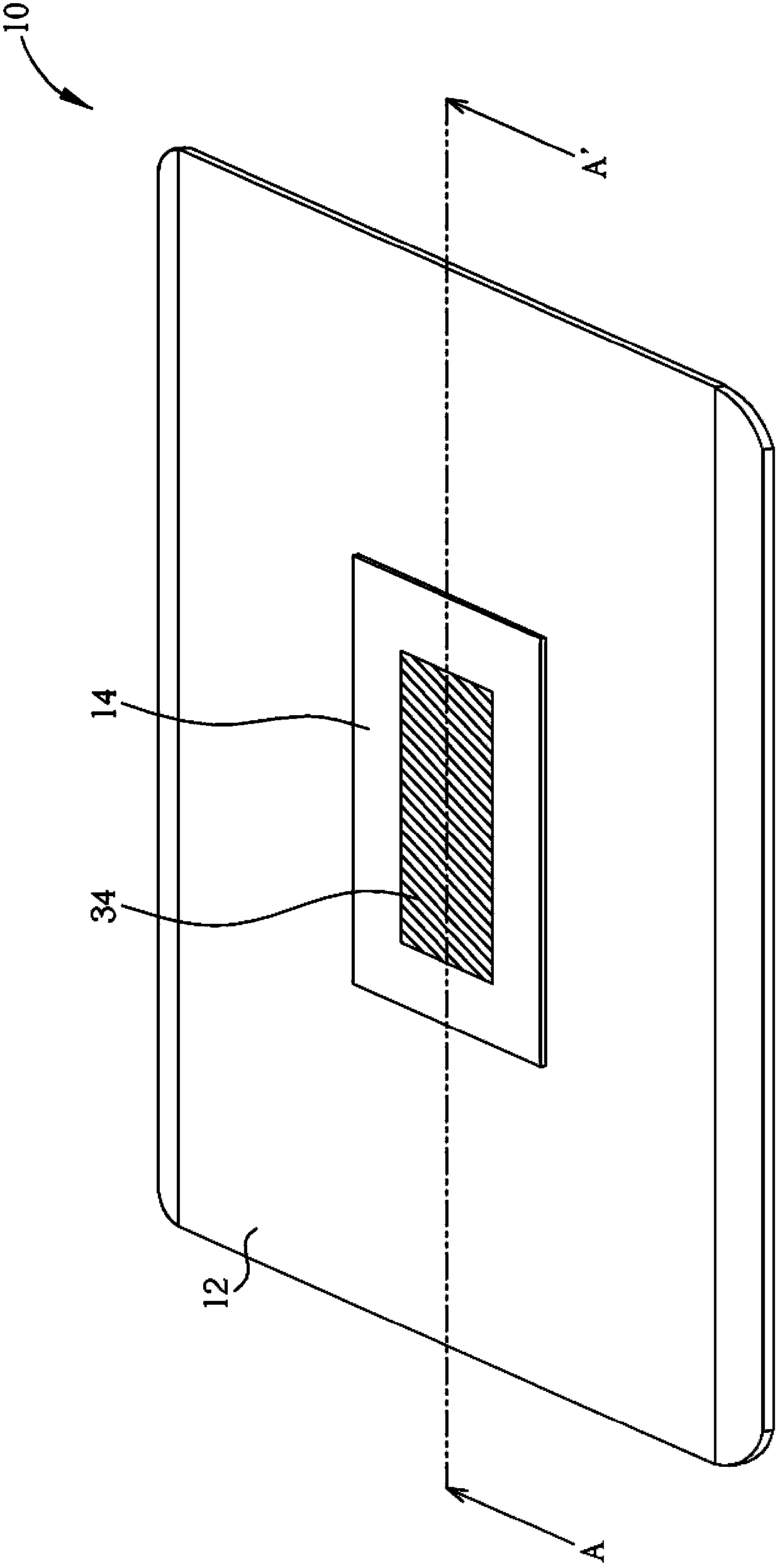
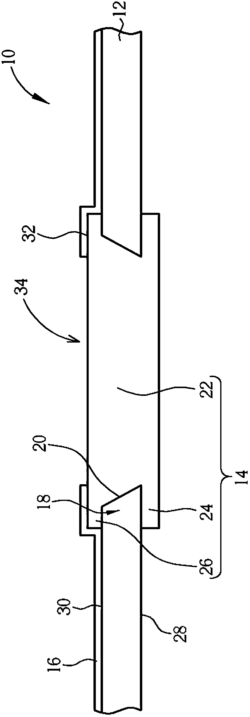
[0022] see figure 1 as well as figure 2 , figure 1 It is a three-dimensional schematic diagram of a top cover 10 proposed according to an embodiment of the present invention, figure 2 for figure 1 A schematic cross-sectional view of the upper cover 10 along the section line A-A'. In this embodiment, the upper cover 10 is applied to the light-emitting housing design of a portable computer device (such as a notebook computer, etc.) with a backlight source, that is to say, through the configuration of the upper cover 10, the portable computer device The light emitted by the backlight source (such as a direct-type backlight source) can be emitted from the light-transmitting plastic part of the upper cover 10, and the detailed structural design of the upper cover 10 is as follows.

[0023] Such as figure 1 as well as figure 2 As shown, the upper cover 10 includes a metal shell 12 , a plastic plate 14 , and a paint layer 16 . The metal shell 12 has a hole structure 18 exte...


PUM


Abstract

The invention provides a method for manufacturing cover of portable computer and cover thereof. The cover includes a metal housing with a hole structure, and a plastic sheet on the metal housing which is related to the hole structure and is formed by injection moulding technology for embedding into the metal housing, and the two strucutre mutually form the cover. The hole strucutre extendes inwardly for forming an inclined flange. The plastic sheet comprises an inward projection and a hole strucutre filling part, and the hole structure filling part is connected in the hole strucutre, and the inward projection is opposite to the hole structure filling part and extends outwardly from the hole strucutre and is formed on the inner surface of the metal housing, thereby mutually clamping the inclined flange with the hole structure filling part.

Description

technical field [0001] The invention relates to a method for manufacturing an upper cover and the upper cover thereof, in particular to a method for manufacturing the upper cover and the upper cover for clamping the inclined-plane flange of the hole structure on the metal shell by using a plastic plate. Background technique [0002] Under the current trend of portable computer devices (such as notebook computers, etc.) emphasizing thinness, lightness and compactness, portable computer devices usually adopt an all-metal upper cover design. However, if a portable computer device wants to use a light-emitting upper cover The design of the upper cover or the antenna on the upper cover is intended to have the function of wireless signal transmission. The design of the above-mentioned all-metal upper cover will cause the light to be unable to transmit due to the metal material being impervious to light and having the characteristics of Electromagnetic Interference (EMI). Problems ...

Claims


Application Information

Patent Timeline
Patent Type & Authority Applications(China)
IPC IPC(8): G06F1/16
Inventor 陈宏仁李忠弼张梓怡
Owner MSI ELECTRONICS KUN SHAN
Why Eureka
Try Eureka