Rotor assembling method, and control device for rotor assembly apparatus

An assembly method and a technology for assembling devices, which are applied in the direction of electromechanical devices, manufacturing stator/rotor bodies, electric components, etc., can solve the problems of low performance of rotating electrical machines, achieve the purpose of suppressing the reduction of insertability, improving performance, and reducing positional deviation Effect

Pending Publication Date: 2022-01-28
TOYOTA JIDOSHA KK
View PDF9 Cites 0 Cited by
  • Summary
  • Abstract
  • Description
  • Claims
  • Application Information

AI Technical Summary

Problems solved by technology

However, in each section perpendicular to the longitudinal direction, the larger the size of the hole compared to the size of the permanent magnet, the larger the gap between the rotor core and the permanent magnet, and the lower the performance of the rotating electrical machine

Method used


Image

  • Rotor assembling method, and control device for rotor assembly apparatus
  • Rotor assembling method, and control device for rotor assembly apparatus
  • Rotor assembling method, and control device for rotor assembly apparatus

Examples


Embodiment 1

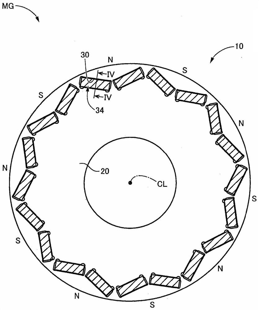
[0059] figure 1 It is a cross-sectional view illustrating a schematic structure of a rotor 10 to which the present invention is applied. figure 1 is a cross-sectional view of the rotor 10 perpendicular to the axis CL. Hereinafter, the "direction parallel to the axis line CL" is simply referred to as "the axis line CL direction".

[0060] The rotor 10 is disposed, for example, on a vehicle rotating electrical machine MG mounted on a hybrid vehicle or an electric vehicle, which is a drive source for traveling of the vehicle. The vehicle rotating electrical machine MG is a rotating electrical machine having a function as an electric motor (motor) and a function as a generator (generator), that is, a so-called motor generator. The vehicle rotating electric machine MG is a magnet-embedded rotating electric machine, and includes a stator having an unillustrated field winding, and a rotor 10 in which permanent magnets 34 are embedded or inserted.

[0061] The rotor 10 has a cylind...

Embodiment 2

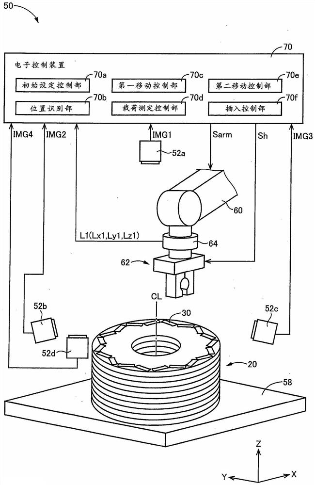
[0114] Figure 6 It is a figure explaining the schematic structure of the rotor assembly apparatus 150 used for the assembly method of the rotor 10 in Example 2 of this invention, and is a figure explaining the main part of the control function used for various control in the rotor assembly apparatus 150. . The structure of the rotor assembly device 150 is substantially the same as that of the rotor assembly device 50 in the first embodiment described above, but the main difference is that a fixed table 158 and a load sensor 164 are provided instead of the fixed table 58 and the load sensor 64 . Therefore, in the present embodiment, the description will focus on the parts that are different from the above-mentioned first embodiment, and the same reference numerals will be assigned to the parts that are substantially common in function with the above-mentioned first embodiment, and the description will be omitted as appropriate. .

[0115] The fixing table 158 fixes and holds...


PUM


Abstract

The present invention provides a method for assembling a rotor and a control device for a rotor assembling device that can reduce the gap between the rotor core and a permanent magnet while suppressing the decrease in the insertability of the permanent magnet. The method of assembling a rotor (10) includes a) a first moving step of moving the permanent magnet (34) such that an end (34t1) of the permanent magnet faces an opening of an insertion slot (30op); b) a load measuring step of moving the permanent magnet towards the plumb line direction, with one end approaching the opening, and measuring a load (L1) applied to the permanent magnet by utilizing a load sensor (64); c) a second moving step of moving the permanent magnet based on the measured load information to decrease a position offset (G) between the permanent magnet and the insertion slot observed in the plumb line direction, and separating one end from the opening in the plumb line direction; and d) an insertion step of descending the permanent magnet in the plumb line direction to insert the permanent magnet into the insertion slot.

Description

technical field [0001] The present invention relates to a method of assembling a rotor in a magnet-embedded rotating electrical machine having permanent magnets, and to a control device for the rotor assembling device. Background technique [0002] There is known a rotor in which permanent magnets are inserted into holes of a rotor core and fixed with an adhesive or the like. For example, the rotor assembly method described in Patent Document 1 is like this. In the method of assembling the rotor described in Patent Document 1, the permanent magnets are positioned using a jig and inserted into the holes. [0003] prior art literature [0004] patent documents [0005] Patent Document 1: International Publication No. 2014 / 58978 [0006] In addition, when inserting the permanent magnet into the hole, if a positional shift occurs between the permanent magnet and the hole, there is a possibility that the permanent magnet cannot be inserted into the hole. Therefore, in order ...

Claims


Application Information

Patent Timeline
Patent Type & Authority Applications(China)
IPC IPC(8): H02K15/03
CPCH02K15/03H02K1/2766H02K1/28H02K1/276
Inventor 武岛健太
Owner TOYOTA JIDOSHA KK
Why Eureka
Try Eureka