
Stress peening device

A shot peening and spray gun technology is used in explosion generating devices, used abrasive treatment devices, spray guns, etc. It can solve problems such as large deformation of workpieces and uneven coverage, achieve high processing efficiency and improve product quality. , the effect of improving efficiency

Active Publication Date: 2013-02-06
AECC AVIATION POWER CO LTD
View PDF8 Cites 11 Cited by
  • Summary
  • Abstract
  • Description
  • Claims
  • Application Information

AI Technical Summary

Problems solved by technology

[0005] In order to overcome the problem of uneven coverage in the prior art, which leads to large deformation of the workpiece, the present invention proposes a shot peening device

Method used


Image

  • Stress peening device
  • Stress peening device
  • Stress peening device

Examples


Embodiment Construction

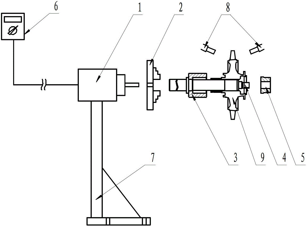
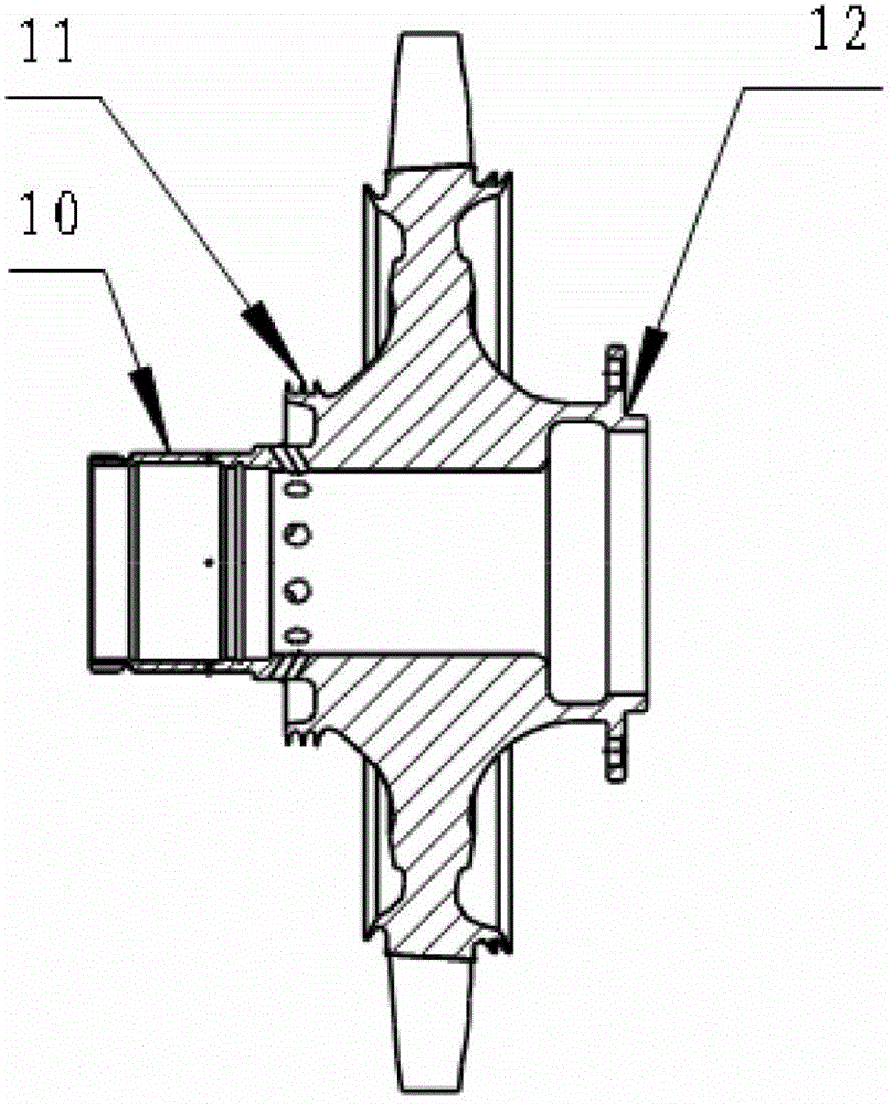
[0030] This embodiment is a vertically rotating double-sided shot peening device, including a motor 1, a workbench 2 with a three-jaw chuck, a front stopper 3, a support rod 4, a rear stopper 5, and a speed regulator 6 And support seat 7. in:

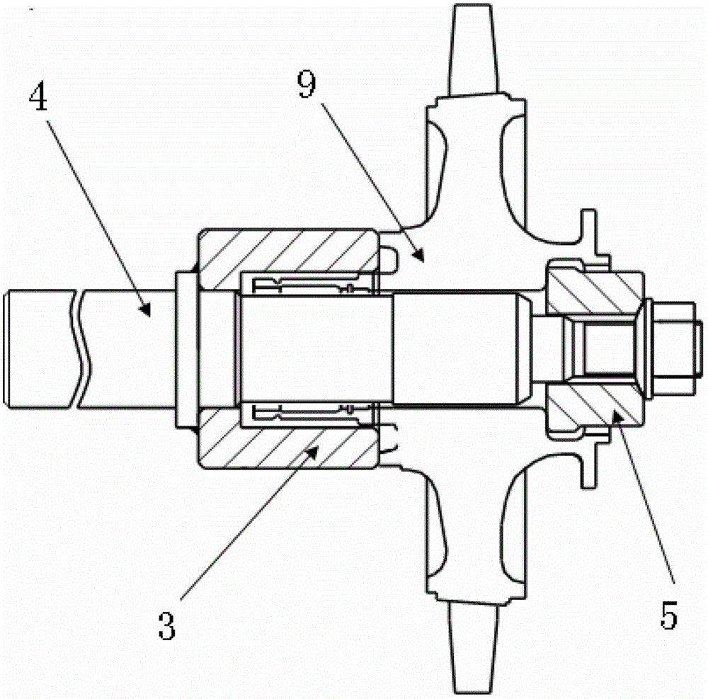
[0031] The motor 1 is fixed on the support base 7 . The workbench 2 is installed on the output shaft of the motor 1, and one surface of the workbench 2 has a three-jaw chuck. One end of the support rod 4 is installed in the three-jaw chuck, and a workpiece 9 is installed at the other end. The front stopper 3 is sleeved on the support rod 4 and located between the worktable 2 and the workpiece 9 , and one end surface of the front stopper 3 is attached to one end surface of the workpiece 9 . The back stop 5 is sleeved on the support rod 4 , and one end surface of the back stop 5 is attached to the other end surface of the workpiece 9 .

[0032] There are 2 spray guns 8, which are fixed on the top of the workpiece 9 at one end of the s...


PUM


Abstract

The invention discloses a stress peening device which adopts the structure that a motor is fixed on a supporting seat; a working table is mounted on an output shaft of the motor; a three jaw chuck is arranged on one surface of the working table; one end of a supporting rod is mounted in the three jaw chuck, and a workpiece is mounted at the other end of the supporting rod; a front stop block is arranged on the supporting rod in a sleeving manner, and is positioned between the working table and the workpiece; a rear stop block is arranged on the supporting rod in a sleeving manner; one end surface of the rear stop block is jointed with the other end surface of the workpiece; and two spray guns are fixed above the workpiece at one end of the supporting rod through a retaining rod at the top of a work chamber of a shot blasting machine, and are distributed on two sides of the supporting rod. A routine horizontal shot blasting way is changed into a vertically rotating shot blasting way, the opposite spraying on two sides of the workpiece by the two spray guns is realized, due to mutual cancellation of deformation of the two sides of the workpiece, the deformation of the workpiece in the stress peening process is reduced effectively, the out-of-tolerance or rejection loss is reduced, the secondary processing is reduced, and the product quality is improved.

Description

technical field [0001] The invention relates to the field of shot peening, in particular to a vertically rotating double-face shot peening device. Background technique [0002] Shot peening is a process in which the high-speed moving shot jet sprays the surface of the material and causes the surface to undergo plastic deformation. Reasonable use of the residual stress field and deformed microstructure introduced into the surface plastic deformation layer can improve the fatigue fracture of the metal material. Stress corrosion cracking resistance. Shot peening technology has been widely used in aerospace, automobile and shipbuilding and other fields. [0003] In traditional shot peening, the shot peening layer is obtained by putting the workpiece into a special shot peening equipment, and using compressed air as the power to drive the pellets to impact the surface of the workpiece. At present, the relevant domestic shot peening equipment workbenches are horizontal work turn...

Claims


Application Information

Patent Timeline
IPC IPC(8): B24C3/02B24C3/32B24C5/02B24C9/00
Inventor 胡云辉曾惠元刘保华杨明芸文瑞
Owner AECC AVIATION POWER CO LTD
Learn More