Core-pulling self-locking mechanism

A self-locking and core-pulling technology, applied in the field of injection molds, can solve the complex problems of the whole set of molds, achieve the effect of simple core-pulling mechanism, reduce processing difficulty and production cost

Active Publication Date: 2013-02-06
佛山市顺德区容声塑胶有限公司
View PDF2 Cites 2 Cited by
  • Summary
  • Abstract
  • Description
  • Claims
  • Application Information

AI Technical Summary

Benefits of technology

This technology makes it easier for an injector machine to produce plastic parts with complex cores that are difficult or expensive to manufacture due to its complexity. It also reduces process difficulties by making sure there's no unnecessary steps needed during assembly.

Problems solved by technology

This patented technical problem addressed in this patents relates to improving the way that injected plastisol (plasma) can escape from certain parts during production without causing damage or malfunctions when trying to remove them manually.

Method used


Image

  • Core-pulling self-locking mechanism

Examples


Embodiment Construction

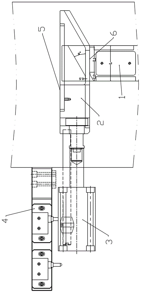
[0019] With reference to the accompanying drawings, a core-pulling self-locking mechanism includes a core-pulling 1 , a core-pulling dial 2 and a core-pulling driving device 3 . The above-mentioned core-pulling driving device is preferably a hydraulic cylinder (oil cylinder), and the stroke switch mechanism 4 can be used to control its stroke. Or release the core-pulling to make it move accordingly, and the movement directions between the core-pulling block and the core-pulling are perpendicular to each other. The above-mentioned core-pulling is placed in the core-pulling T-shaped slot, the top surface of the core-pulling T-shaped slot is a flat surface, the core-pulling block includes a wedge-shaped head and a straight section of the block, and the bottom end surface of the straight section of the block is a flat surface. During the mold closing process, the core-pulling driving device pushes the core-pulling block forward, and the core-pulling block is used to force the core...


PUM


Abstract

The invention discloses a core-pulling self-locking mechanism. The core-pulling self-locking mechanism is characterized by comprising a core, a core puller and a core drive mechanism. A T-grooved top face of the core is a plane. The core puller comprises a puller wedged head and a puller straight section. The bottom face of the puller straight section is a plane. During closing, the core drive device pushes the core puller to move forward, the core is urged to correspondingly move by the core puller until the puller straight section starts abutting to the T-grooved top face of the core, the bottom face of the puller straight section starts contacting with the T-grooved top face of the core to form locking faces, the core just reaches a set travel and stops moving, the core drive device continues to push the core puller to move forward, and the locking faces increase with the moving until the core puller reaches the set position. The opening process is right reverse to the closing process. By the use of the core-pulling self-locking mechanism, the existing complex injection mould core-pulling mechanism is simple and reliable, and processing difficulty and production cost of injection moulds can be lowered greatly.

Description


Claims


Application Information

Patent Timeline
Owner 佛山市顺德区容声塑胶有限公司
Why Eureka
Try Eureka