Multi-spring constrained quadrilateral foldable and extendable suspension type six-wheel vehicle-mounted mechanism
A quadrilateral mechanism and quadrilateral technology, applied in the direction of off-ground vehicles, etc., to achieve strong adaptability, increase the overall size, and ensure stability
- Summary
- Abstract
- Description
- Claims
- Application Information
AI Technical Summary
Problems solved by technology
Method used
Image

Examples
specific Embodiment approach 1
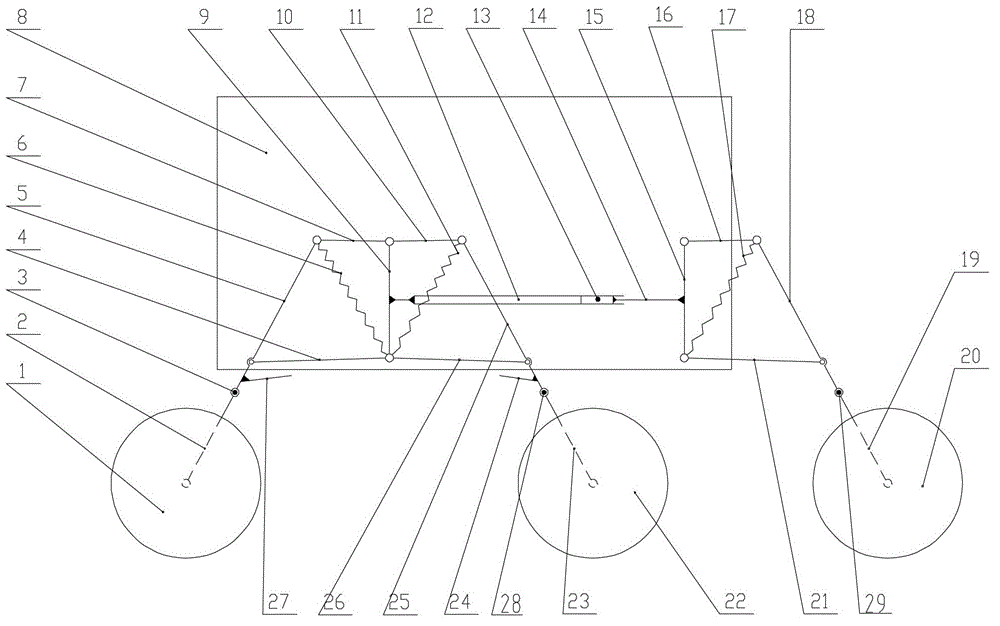
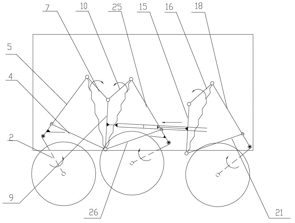
[0008] Specific implementation mode one: combine Figure 1-Figure 3 Describe this embodiment, the mechanism of this embodiment includes the first wheel 1, the first lever 2, the first rotation locking device 3, the second lever 4, the third lever 5, the first extension spring 6, the fourth lever 7, Seventh rod 9, fifth rod 10, second tension spring 11, guide rail 12, locking pin 13, slider 14, tenth rod 15, eleventh rod 16, third tension spring 17, twelfth rod 18, the fourteenth rod 19, the third wheel 20, the thirteenth rod 21, the second wheel 22, the ninth rod 23, the sixth rod 25, the eighth rod 26, the second rotation locking device 28 and the third rotation locking Device 29, one end of the first rod 2 is hinged with the first wheel 1, the other end of the first rod 2 is hinged with one end of the third rod 5 through the first rotation locking device 3, and the other end of the third rod 5 is connected with the fourth rod One end of 7 is hinged, the other end of the fou...
specific Embodiment approach 2
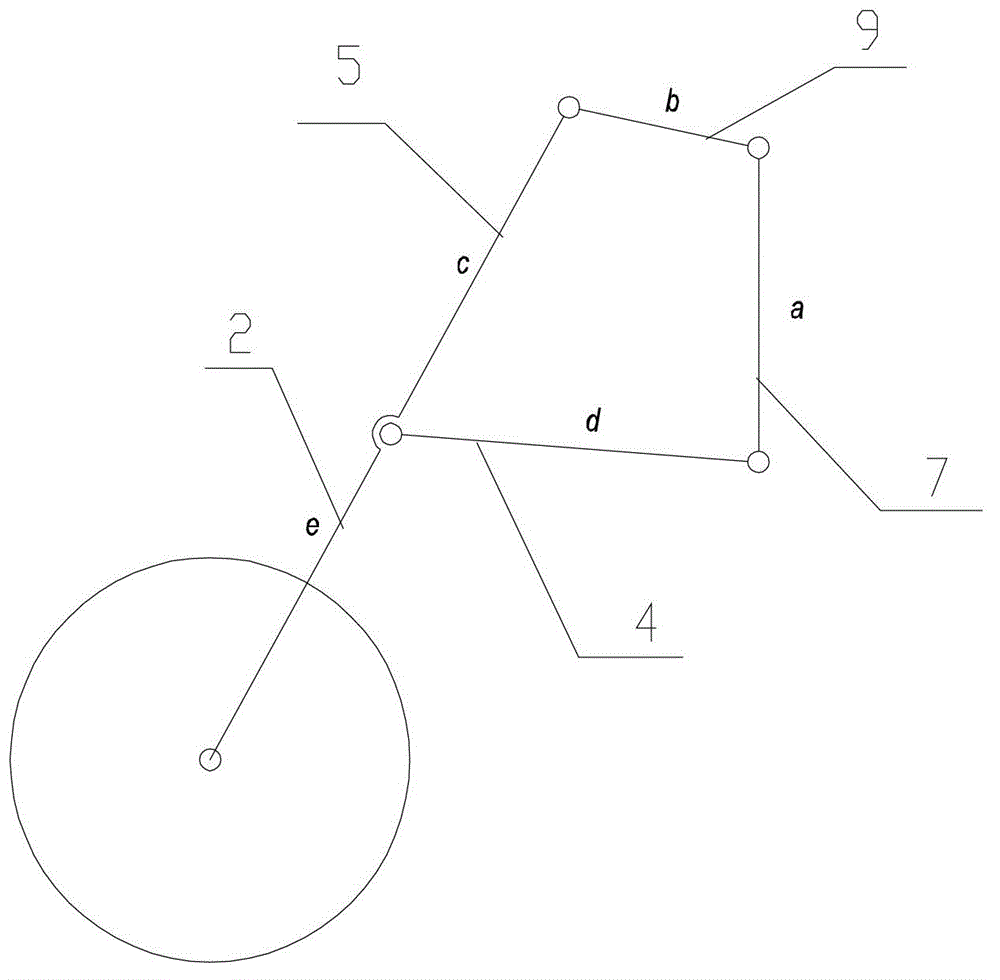
[0010] Specific implementation mode two: combination figure 1 Describe this embodiment, the first spring-constrained quadrilateral mechanism of this embodiment, the second spring-constrained quadrilateral mechanism and the third spring-constrained quadrilateral mechanism are the same, the first spring-constrained quadrilateral mechanism defines the length of the seventh rod 9 as a, the fourth rod The length of 7 is b, the length of the third rod 5 in the first spring constrained quadrilateral mechanism is c, the length of the second rod 4 is d, the first rod 2 and the third rod 5 are outside the first spring constrained quadrilateral mechanism Length is e, and wherein c=d=e, a=1.6b, c=1.9b, promptly along with the 4th bar 7 rotates around the hinge point of the 4th bar 9 and the 7th bar 9, the locus of the first wheel 1 is a straight line. Other implementation manners are the same as the specific implementation manner 1.
specific Embodiment approach 3
[0011] Specific implementation mode three: combination Figure 4 Describe this embodiment, the first rotation locking device 3 of this embodiment includes a first snap ring 3-1, a first cylindrical pin 3-3, a first taper pin 3-4, a first support plate 3-5, a first Taper pin guide sleeve 3-6, the first spring cap 3-7, the first spring 3-8 and two first spacers 3-2, the first support plate 3-5 is L-shaped, the side of the third rod 5 The wall is affixed to one end of the horizontal section of the first support plate 3-5, and the side wall of the vertical section of the first support plate 3-5 is affixed to one end of the first taper pin guide sleeve 3-6, and the first taper pin The other end of the guide sleeve 3-6 is fitted with the first spring cap 3-7 and the two are threaded, one end of the first taper pin 3-4 is fitted with the first spring 3-8 and this end passes through the first rod 2, The vertical section of the first support plate 3-5 is located in the first taper pin...
PUM
 Abstract
Description
Claims
Application Information
 - R&D
- Intellectual Property
- Life Sciences
- Materials
- Tech Scout
- Unparalleled Data Quality
- Higher Quality Content
- 60% Fewer Hallucinations
Browse by: Latest US Patents, China's latest patents, Technical Efficacy Thesaurus, Application Domain, Technology Topic, Popular Technical Reports.
© 2025 PatSnap. All rights reserved.Legal|Privacy policy|Modern Slavery Act Transparency Statement|Sitemap|About US| Contact US: help@patsnap.com