A kind of high tensile load composite material pipe fitting and its preparation method

A composite material and composite material layer technology, applied in the field of composite material forming, can solve problems such as the inability to meet high tensile load bearing requirements, achieve the effect of weakening the tendency of early failure, increase tensile load, and solve local bridging

Active Publication Date: 2015-12-16
AEROSPACE RES INST OF MATERIAL & PROCESSING TECH +1
View PDF7 Cites 1 Cited by
  • Summary
  • Abstract
  • Description
  • Claims
  • Application Information

AI Technical Summary

Problems solved by technology

Traditional domestic composite material pipe assemblies mainly bear compressive loads. The connection between composite materials and metals is mostly in the form of rubber screws, which can withstand large compressive loads, but cannot meet the load-bearing requirements of high tensile loads.

Method used


Image

  • A kind of high tensile load composite material pipe fitting and its preparation method
  • A kind of high tensile load composite material pipe fitting and its preparation method
  • A kind of high tensile load composite material pipe fitting and its preparation method

Examples


Embodiment 1

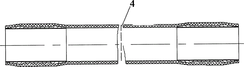
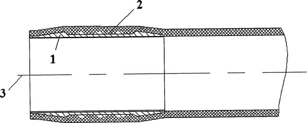
[0023] Such as figure 1 with figure 2 As shown, a high tensile load composite material pipe fitting, the pipe fitting includes an embedded part 1 and a composite material layer 2; the composite material layer 2 is coated on the periphery of the embedded part 1,

[0024] There is one embedded part 1 at each end of the pipe fitting; each embedded part 1 is symmetrical up and down with respect to the center line 3 of the pipe fitting, and the two embedded parts 1 are left-right symmetrical about the central axis 4 of the pipe fitting;

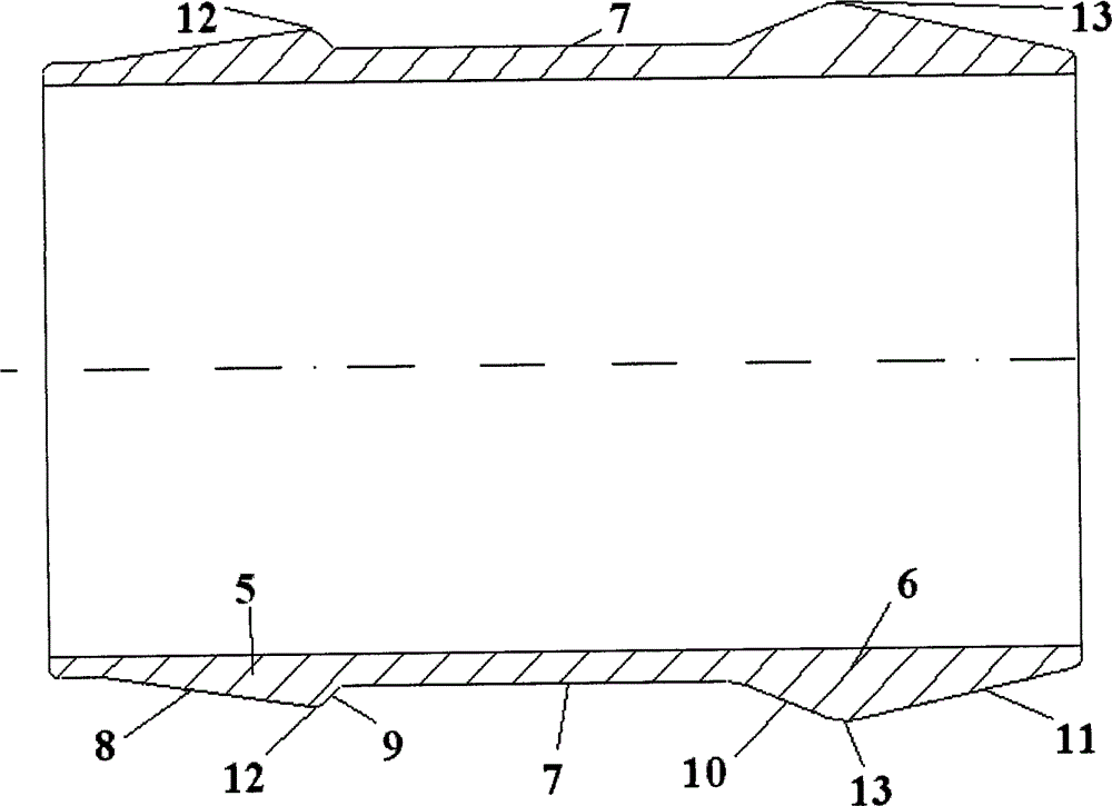
[0025] Such as image 3 with Figure 4 As shown, the embedded part 1 has a hollow cone angle structure, and there are two cone angle structures of the embedded part 1, which are the cone angle A5 and the cone angle B6; the area formed between the cone angle A5 and the cone angle B6 is a groove 7;

[0026] The cone angle A5 is composed of one ascending line A8 and one descending line A9, the angle between the ascending line A8 and the center l...

Embodiment 2

[0038] Same as Example 1, the difference is that the taper angles of the embedded parts are 4, such as Image 6 with Figure 7 shown.

[0039] The implementation plan takes key technologies such as metal joint structure optimization and winding forming process optimization as the core, and carries out technological research one by one to complete the development of light-weight and heavy-duty composite material pipes.


PUM

PropertyMeasurementUnit
diameteraaaaaaaaaa
lengthaaaaaaaaaa

Abstract

The invention relates to a pipe fitting made of composite material with high-tensile load and a manufacturing method of the pipe fitting and belongs to the technical field of composite material forming. The pipe fitting comprises two embedded parts and a composite material layer. The composite material layer is coated on the outer peripheries of the embedded parts, and the two embedded parts are arranged at two ends of the pipe fitting. The embedded part is provided with more than two cone angles, and an area formed between adjacent two cone angles is a groove. Each cone angle comprises an ascending line and a descending line, an included angle between the ascending line and a central line of the cone angle on the outermost side of the pipe fitting is smaller than an included angle of the ascending line and a central line of the cone angle on the inner side, and the diameter of a sharp point of the cone angle on the outermost side is smaller than that of a sharp point of the cone angle on the inner side. The cone angle on the outermost side of the fitting is one cone angle at the leftmost end of the pipe fitting or one cone angle at the rightmost end of the pipe fitting. The pipe fitting, which is made of composite material and manufactured by the method, has tensile load of 40t, and actual tensile fracture load of 48t.

Description

technical field [0001] The invention relates to a high tensile load composite material pipe fitting, a high tensile load composite material pipe fitting and a preparation method thereof, belonging to the technical field of composite material forming. Background technique [0002] The suspension device of the second-level box section of the launch vehicle core bears a large tensile load, and there are also bending, shearing, and compressive loads, and the mechanical environment is complex. In order to achieve structural weight reduction, the suspension device of the second-level box section of the core adopts a rod system structure, and the composite material pipe structure is used to replace the metal pipe structure. The tensile load of a single tube needs to reach about 40t, and the lightweight and heavy-duty composite material tube assembly has not yet been used in domestic models. [0003] Composite rod system structure has been applied in the structure of existing forei...

Claims


Application Information

Patent Timeline
Patent Type & Authority Patents(China)
IPC IPC(8): F16S3/00B29C53/56
Inventor 张建宝林松王俊锋孙文文张蕾赵文宇刘伟范佳
Owner AEROSPACE RES INST OF MATERIAL & PROCESSING TECH
Why Eureka
Try Eureka