Light emitting diode (LED) lighting device with stabilizing device

A technology of LED lighting and LED lamp beads, which is applied to lighting devices, components of lighting devices, lighting and heating equipment, etc., and can solve problems such as complex structures, reducing flicker effects, and increasing luminous time

Inactive Publication Date: 2013-02-06
DUJIANGYAN HUAGANG ELECTRONICS TECH
View PDF1 Cites 1 Cited by
  • Summary
  • Abstract
  • Description
  • Claims
  • Application Information

AI Technical Summary

Problems solved by technology

[0005] Due to the unidirectional conduction of light-emitting diodes, in order to maintain stable light emission in lighting applications, the current practice is to use direct current for driving. A rectifier transformer is attached to the lamp for AC / DC conversion, which will bring additional power loss and reduce the overall life of the product. Therefore, Chinese patent document CN101208813B discloses a "light-emitting device for AC power operation 》, the device comprises a light-emitting diode chip, the light-emitting diode chip has an array of series-connected light-emitting units, and switching blocks respectively connected to the nodes between these light-emitting units, wherein when the array is connected to an AC voltage power supply and is powered by the AC When driven by a voltage power supply, these light-emitting units are turned on and off sequentially by means of these switching blocks. This light-emitting device can turn on these arrays sequentially under AC power, and then turn off these arrays in the reverse order, thereby reducing the flicker effect and The luminous time can be increased, but this solution has a complex structure and high requirements on the manufacturing process

Method used


Image

  • Light emitting diode (LED) lighting device with stabilizing device
  • Light emitting diode (LED) lighting device with stabilizing device
  • Light emitting diode (LED) lighting device with stabilizing device

Examples


Embodiment Construction

[0023] The present invention will be further elaborated below in conjunction with the accompanying drawings.

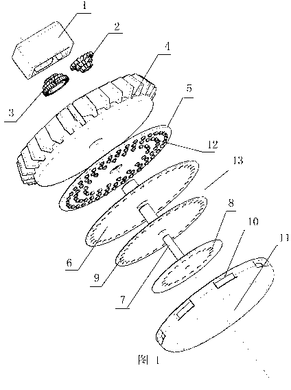
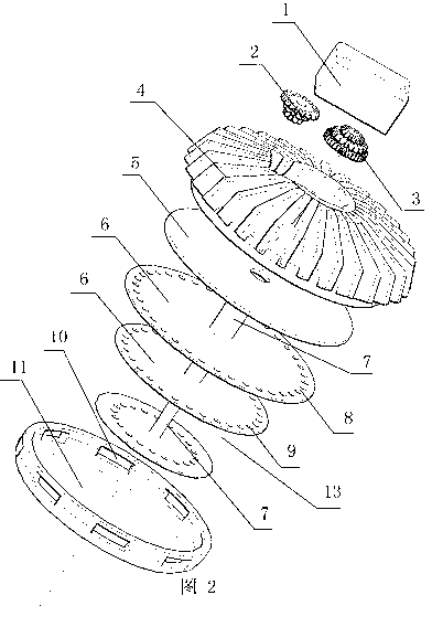
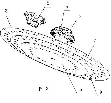
[0024] like Figure 1 to Figure 3 As shown, the LED lighting device with a stabilizing device includes: a lamp body 4 realized by a metal structure, an LED lamp bead 12 welded on an aluminum substrate 5, a luminous member 13 with a concentrically stacked luminous ring structure, The lampshade 11, and the driver 1 including the AC drive power supply and the luminous element drive system, the luminous element 13 includes three luminous ring plates 6, each luminous ring plate 6 is disc-shaped, and the disc-shaped base material of transparent material A layer of long afterglow material is superimposed on the edge position of the long afterglow layer. The long afterglow layer is in the shape of a ring, forming a luminous ring 8. There are evenly spaced through holes 9 penetrating in the luminous ring 8. The through holes 9 are the transparency of the luminous ring 8. part...


PUM


Abstract

The invention discloses a light emitting diode (LED) lighting device with a stabilizing device. The LED lighting device comprises a lamp body (4), LED lamp beads (12) and an alternating current (AC) driving power source, wherein the LED lamp beads (12) are grouped and connected with the AC driving power source through a circuit; and each group of LED lamp beads (12) is turned on and off in time sequence in a grouped manner under the drive of the AC driving power source. The LED lighting device further comprises a driving system and a light emitting piece (13), wherein the light emitting piece (13) can rotate round a shaft under the support of the driving system; the grouped distributing structure of the LED lamp beads (12) is matched with the structure of the light emitting piece (13); the light emitting piece (13) is positioned at the front ends of the LED lamp beads (4) to shield part of the the LED lamp beads (12); and the time sequence of rotating motion of the light emitting piece (13) is matched with the on-off time sequence of each group of LED lamp beads (12). The lighting device has the advantages that the light output quantity is approximately constant and the lamp beads are evenly distributed.

Description

[0001] Technical field [0002] The invention involves the field of lighting equipment, especially a lighting light that can adapt to AC -drive drive work with LED as its main light source. [0003] Background technique [0004] Compared with incandescent lamps and energy -saving lamps, LED (light -emitting diode) has the advantages of energy saving, durability, and pollution -free. It is regarded as the most promising next -generation lighting method, which has attracted widespread attention.The basic light emitting principle of light emitting diode is: During the composite of the carrier in the semiconductor, the excess energy released caused the photons to launch, and the light waves of various colors such as red and blue belongWith outstanding advanced nature, these unique principles and characteristics of LED not only bring the superiority of LED as the use of light sources, but also put forward a series of new requirements for LED lighting applications. For example, Large h...

Claims


Application Information

Patent Timeline
Patent Type & Authority Applications(China)
IPC IPC(8): F21V14/02F21V17/00F21V19/00F21Y101/02F21Y115/10
Inventor 陈刚
Owner DUJIANGYAN HUAGANG ELECTRONICS TECH
Why Eureka
Try Eureka