
USB (universal serial bus) 3.0 connector and manufacturing method thereof

A technology of connectors and contact pieces, applied in the direction of connection, fixed/insulated contact components, circuit/collector components, etc., can solve the problems of increased defective rate, many manufacturing steps, poor production efficiency, etc., and reduce the number of components , Reducing manufacturing steps and reducing production costs

Inactive Publication Date: 2013-02-06
BAIRONG ELECTRONICS
View PDF3 Cites 0 Cited by
  • Summary
  • Abstract
  • Description
  • Claims
  • Application Information

AI Technical Summary

Problems solved by technology

[0015] 1. The USB3.0 connector 10 uses the plastic positioning block 14 to ensure the space and positioning between the first terminal unit 12 and the second terminal unit 13. In order to assemble the plastic positioning block 14 and the For the second pin 134, in steps 22 to 25, the second pin 134 must extend along the front and rear direction, because the first terminal unit 12 is not positioned, and the plastic positioning block 14 is assembled. It is easy to touch the first terminal unit 12, causing the first terminal unit 12 to be skewed and increasing the defective rate
[0016] 2. The plastic positioning block 14 must be used to avoid contact between the first pin 124 and the second pin 134. There are a large number of components and many manufacturing steps, resulting in high production costs and poor production efficiency. Shortcomings
[0017] 3. The back cover 157 only has an aesthetic function for the USB3.0 connector 10, but because the back cover 157 is directly arranged on the rear end of the top sheet 152, consumers cannot choose whether to install the back cover 157, and cannot lower the cost
[0018] 4. There is no positioning design between the metal shell 15 and the insulating body 11, which cannot effectively prevent the metal shell 15 from being separated from the insulating body 11, which affects the quality

Method used


Image

  • USB (universal serial bus) 3.0 connector and manufacturing method thereof
  • USB (universal serial bus) 3.0 connector and manufacturing method thereof
  • USB (universal serial bus) 3.0 connector and manufacturing method thereof

Examples


Embodiment Construction

[0064] The present invention will be described in detail below in conjunction with the accompanying drawings and embodiments.

[0065] Before going into details, it should be noted that the relative positional terms used in the entire specification, such as "front and rear direction X", "left and right direction Y", "top and bottom direction Z", are based on the normal use orientation and each figure. The direction shown is the reference.

[0066] Such as Figure 12 As shown, the preferred embodiment of the USB3.0 connector of the present invention includes an insulating body 30 , a first terminal unit 40 , a second terminal unit 50 , a housing 60 and a rear cover 70 .

[0067] Such as Figure 12 to Figure 17 As shown, the insulating body 30 includes a base 31, a tongue block 32 extending from the base 31 toward the front end, a clamping block 33 formed from the bottom end of the base 31 toward the front end, and a 31 and a receiving groove 34 formed by a top block 311, a b...


PUM


Abstract

The invention discloses a USB 3.0 connector and a manufacturing method thereof. The USB 3.0 connector comprises an insulation body, a first terminal unit, a second terminal unit and an enclosure sleeved on the exterior of the insulation body. The insulation body comprises a substrate, an accommodating groove arranged at the rear side surface of the substrate, bottom blocks respectively arranged on the base along the front-and-back direction, five shallow slots and four deep slots which are arranged in a staggered manner in sequence along the left-and-right direction, wherein the first pins of the first terminal unit can be arranged in the deep slots respectively, and the second pins and the third pins of the second terminal unit can be respectively arranged in the shallow slots, so that the first pins, the second pins and the third pins can be well positioned and cannot be contacted with each other, the number of elements is reduced, the production cost is reduced, the manufacturing procedures are reduced, and the production quality and efficiency are improved.

Description

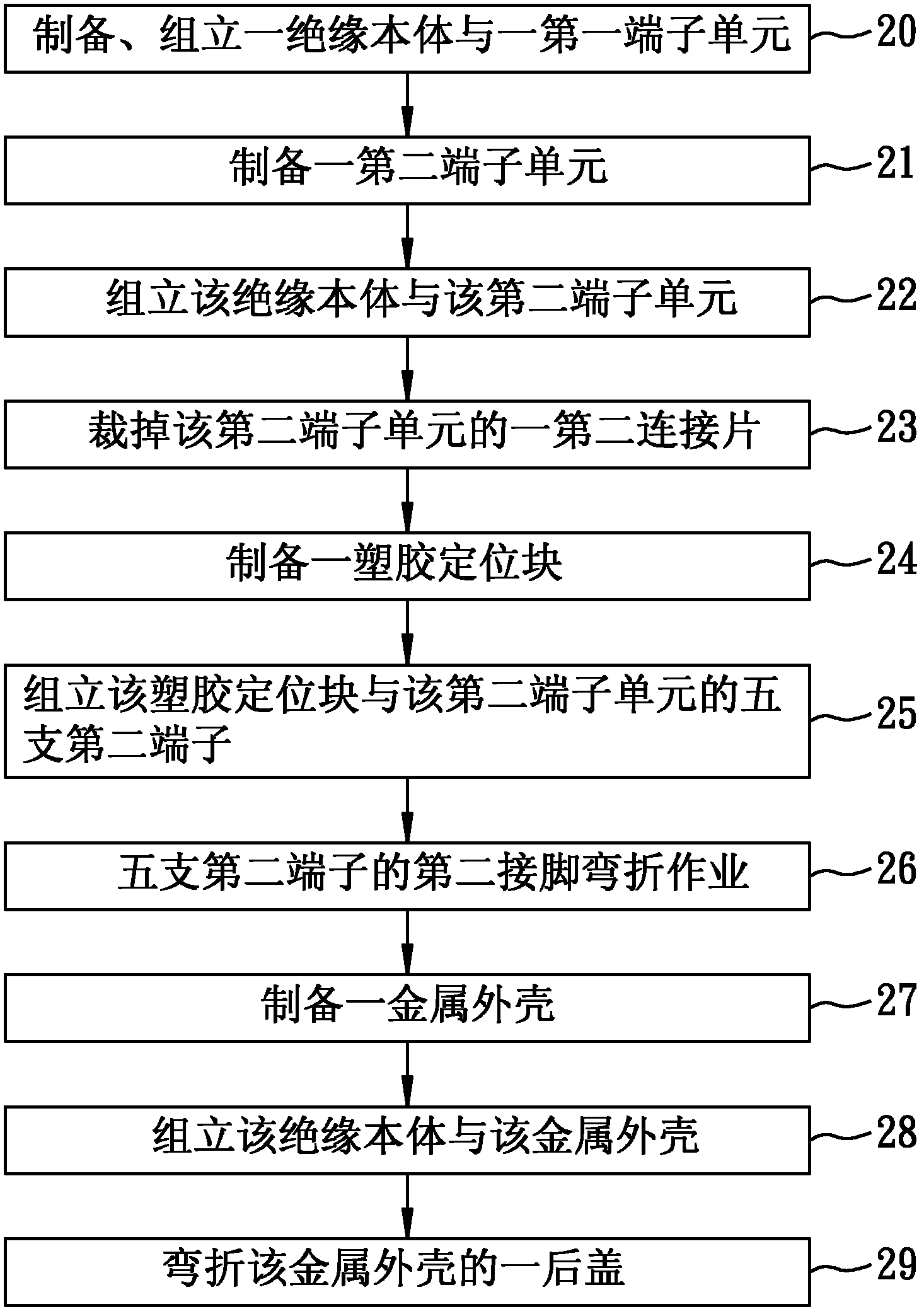
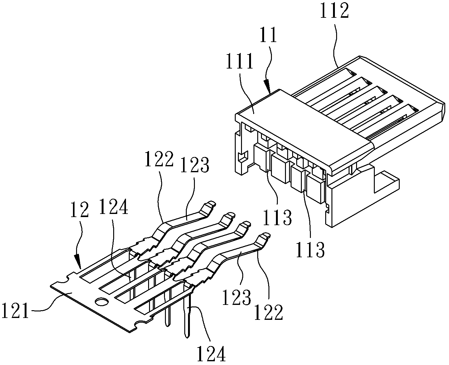
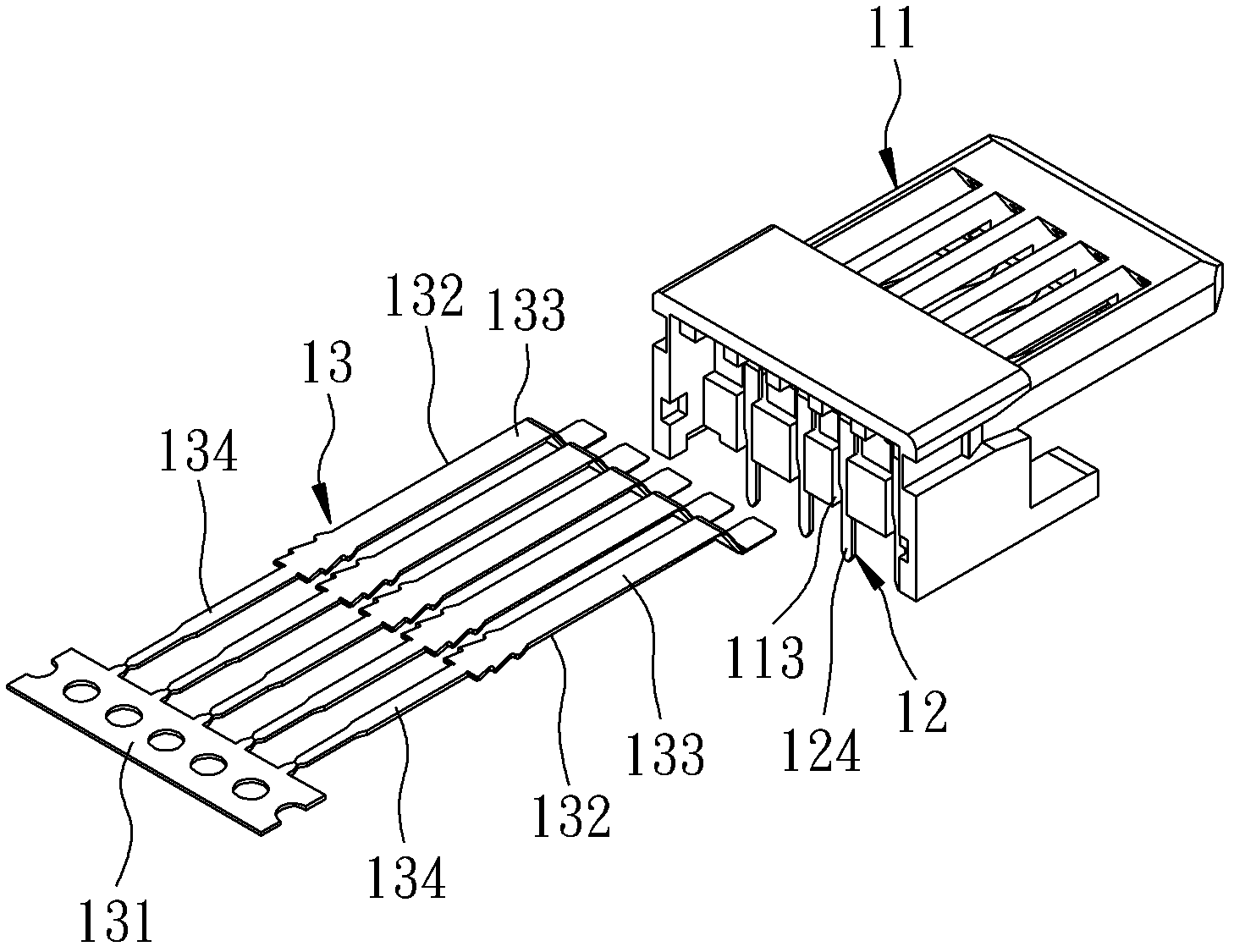
technical field [0001] The invention relates to a connector, in particular to a USB3.0 connector and a manufacturing method thereof. Background technique [0002] The USB (Universal Serial BUS) connector has the function of transmitting signals and power at the same time. Compared with the USB2.0 connector, the USB3.0 connector has the characteristic of speeding up the transmission speed, and has gradually replaced the USB2.0 connector. [0003] Such as figure 1 As shown, the manufacturing method of the general USB3.0 connector 10 includes steps 20 to 29: [0004] Such as figure 1 , figure 2 As shown, step 20 is to prepare and assemble an insulating body 11 and a first terminal unit 12. The insulating body 11 has a base block 111, a tongue block 112 extending from the base block 111 along a front-to-back direction, and There are four positioning slots 113 arranged on the rear side of the base block 111 in the top and bottom directions. The first terminal unit 12 has a f...

Claims


Application Information

Patent Timeline
IPC IPC(8): H01R13/46H01R13/40H01R43/00
Inventor 林志明孙立言
Owner BAIRONG ELECTRONICS
Learn More