BMS (battery management system) and related components

A different, converter technology, applied to vehicle components, electrical components, instruments, etc., can solve the problems of increasing the number of components required for the circuit, controlling the voltage of the output load, and complex circuit structure, etc., to reduce the number of control signals , to avoid damage, the effect of simple circuit structure

Pending Publication Date: 2022-05-27
ZHANGZHOU KEHUA ELECTRIC TECH CO LTD
View PDF0 Cites 0 Cited by
  • Summary
  • Abstract
  • Description
  • Claims
  • Application Information

AI Technical Summary

Problems solved by technology

[0002] The traditional BMS (Battery Management System, battery management system) is equipped with charge-prohibited MOS tubes and discharge-prohibited MOS tubes, which can control the battery such as charge-prohibited and discharge-prohibited when the condition of prohibiting charge or discharge is met, but it can only realize The on-off control of the circuit cannot control the voltage output to the load according to the needs of the load. If you want to output multiple voltages, you need to install an additional DC / DC converter outside the BMS. As a result, the BMS not only needs to control its own forbidden MOS tube and The banning of MOS tubes also requires the control of the DC / DC converter, which requires an increase in the number of control signals, and increases the number of components required for the circuit, making the circuit structure complex

Method used


Image

  • BMS (battery management system) and related components
  • BMS (battery management system) and related components
  • BMS (battery management system) and related components

Examples


Embodiment Construction

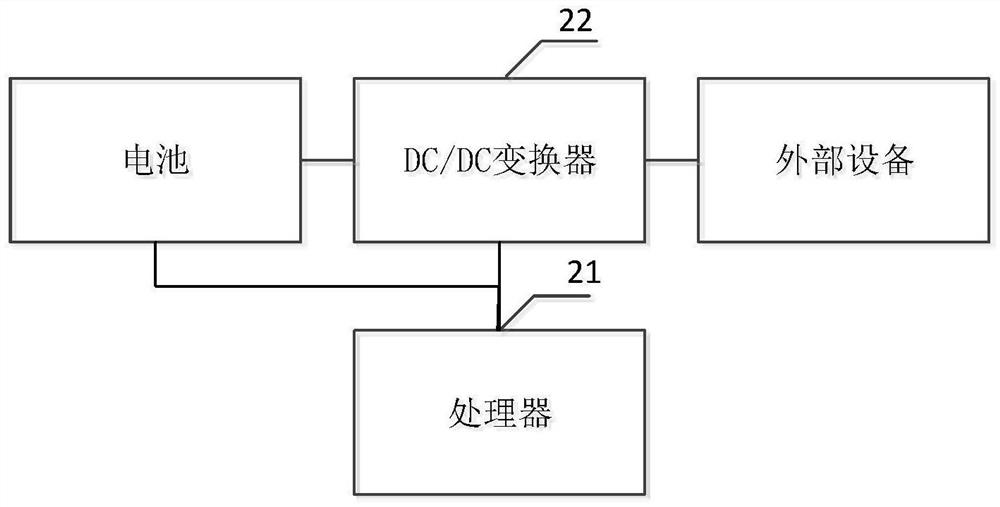
[0027] The core of the invention is to provide a BMS and related components, which reduces the number of components in the circuit, makes the circuit structure simpler, reduces the number of control signals, and makes the control logic simpler, and can be used when multiple batteries are connected in parallel. Ensure that the output voltage of each DC / DC converter is equal to avoid damage to the battery caused by circulating current.

[0028] In order to make the purposes, technical solutions and advantages of the embodiments of the present invention clearer, the technical solutions in the embodiments of the present invention will be clearly and completely described below with reference to the accompanying drawings in the embodiments of the present invention. Obviously, the described embodiments These are some embodiments of the present invention, but not all embodiments. Based on the embodiments of the present invention, all other embodiments obtained by those of ordinary ski...


PUM


Abstract

The invention discloses a BMS and related components, a DC / DC converter is added in the BMS, when the battery discharges, the voltage of the battery can be converted according to the needs of the load and then is supplied to the load, meanwhile, different port voltages can be converted and then are charged for the battery, and meanwhile, a processor can control the DC / DC converter to realize charging forbidding and discharging forbidding of the battery. In other words, the processor only needs to output one signal to achieve control over the DC / DC conversion output voltage and control over charging forbidding and discharging forbidding of the circuit, no additional arrangement of a discharging forbidding MOS tube and a charging forbidding MOS tube is needed, the number of components in the circuit is reduced, the circuit structure is simpler, meanwhile, the number of control signals is reduced, and control logic is simpler. The processor adopts closed-loop regulation to control the output voltage of the DC / DC converters, so that the output voltage of each DC / DC converter can be ensured to be equal when a plurality of batteries are connected in parallel, and the damage to the batteries caused by generated circulating current is avoided.

Description

technical field [0001] The present invention relates to the field of batteries, in particular to a BMS and related components. Background technique [0002] The traditional BMS (Battery Management System, battery management system) is equipped with a forbidden charge MOS tube and a forbidden discharge MOS tube, which can control the battery such as forbidden charge and forbidden discharge when it meets the forbidden charge or forbidden discharge conditions, but it can only realize the control of the battery. The control of circuit on-off cannot control the voltage output to the load according to the needs of the load. If you want to output a variety of voltages, you need to set up an additional DC / DC converter outside the BMS, so that the BMS not only needs to control its own forbidden charge MOS tube and Forbidden MOS tube also needs to control the DC / DC converter, the number of control signals needs to be increased, and the number of components required for the circuit is ...

Claims


Application Information

Patent Timeline
IPC IPC(8): H02M3/158H02J7/00
CPCH02J7/0063H02J7/00032H02J7/0047H02J7/00308H02J7/0031Y02E60/10
Inventor 王定富许勇枝曾益彰陈阳源
Owner ZHANGZHOU KEHUA ELECTRIC TECH CO LTD
Why Eureka
Try Eureka