Twin-screw propelling device for ship

A technology of double propellers and propulsion devices, which is applied in the direction of ship propulsion, propulsion components, ship components, etc., and can solve problems such as unbalanced forces, increased rudder bearings, and affecting safe navigation of ships

Inactive Publication Date: 2013-02-13
JIANGSU HUAYANG HEAVY IND
View PDF0 Cites 3 Cited by
  • Summary
  • Abstract
  • Description
  • Claims
  • Application Information

AI Technical Summary

Problems solved by technology

[0002] The propeller propulsion device is used to push the water flow to obtain the reaction force to move the ship forward. Since there is an angle between the rotation direction of the propeller blade and the propeller axis, when the propeller rotates, the water flow pushed by the propeller blade moves backward in a spiral shape. , because the rudder blades are installed behind the propeller blades (with the direction of the

Method used


Image

  • Twin-screw propelling device for ship

Examples


Embodiment Construction

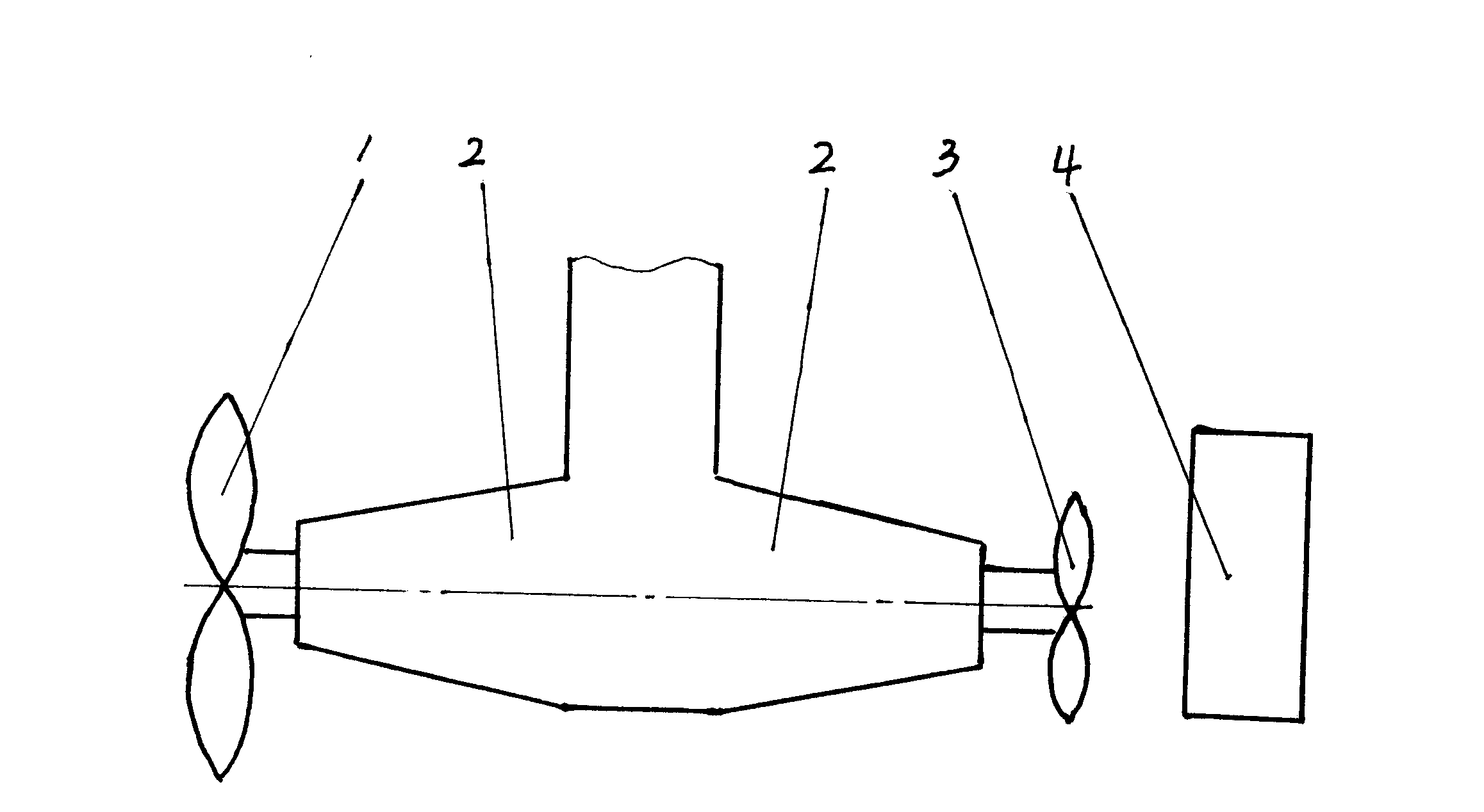
[0009] figure 1 Among them, the propeller seat 2 is fixedly connected to the hull, the main propeller 1 is installed at the front end of the propeller seat 2, the auxiliary propeller 3 is installed at the rear end of the propeller seat 2, the rudder blade 4 is behind the auxiliary propeller 3, and the rudder blade 4 passes through the rudder stock Rotatably installed on the hull (rudder stock is not shown in the figure), the axis of auxiliary propeller 3 coincides with the axis of main propeller 1, the diameter of auxiliary propeller 3 is less than the diameter of main propeller 1, the rotation of the blade on the auxiliary propeller 3 The direction of rotation is opposite to that of the blades on the main propeller 1. The main propeller 1 and the auxiliary propeller 3 are driven by respective transmissions (the transmission is not shown in the figure). During work, the rotation direction of the main propeller 1 is opposite to that of the auxiliary propeller 3. The propelled ...


PUM


Abstract

The invention relates to a ship propelling device, in particular to improvement of a screw propelling device for a ship. A twin-screw propelling device for the ship comprises a screw seat, and a main screw which is rotatably arranged on the screw seat through a transmission device; the screw seat is also provided with an auxiliary screw which is arranged behind the main screw; the axis of the auxiliary screw and the axis of the main screw are parallel to each and near each other; the rotation directions of blades of the auxiliary screw are opposite to the rotation directions of blades of the main screw; and the diameter of the auxiliary screw is smaller than that of the main screw. The twin-screw propelling device for the ship can eliminate or reduce the influence of spiral water flow to ship sailing and a rudder gear, and the ship can sail normally.

Description

technical background: [0001] The invention relates to a ship propulsion device, in particular to an improvement of a ship propeller propulsion device. Background technique: [0002] The propeller propulsion device is used to push the water flow to obtain the reaction force to move the ship forward. Since there is an angle between the rotation direction of the propeller blade and the propeller axis, when the propeller rotates, the water flow pushed by the propeller blade moves backward in a spiral shape. , because the rudder blades are installed behind the propeller blades (with the direction of the propeller pointing to the bow as the front), the helical backward moving water flow acting on the rudder blades will cause the force on both sides of the rudder blades to be unbalanced, thus affecting the safety of the ship How to eliminate or reduce the impact of spiral water flow on ship navigation and rudder gear due to navigation and increase the wear of rudder bearings and ru...

Claims


Application Information

Patent Timeline
IPC IPC(8): B63H5/10
Inventor 丁郁华丁晓阳
Owner JIANGSU HUAYANG HEAVY IND
Why Eureka
Try Eureka