Mini vacuum pump

A technology of miniature vacuum pumps and shells, which is applied in the direction of pumps, pumps with flexible working elements, and liquid variable capacity machinery, etc., which can solve the problems of large operating current and output power of motors, energy consumption, and large operating noise of micro air pumps. Achieve the effects of reduced operating current, low energy consumption, and good vacuum

Active Publication Date: 2015-04-22
XIAMEN CONJOIN ELECTRONICS TECH
View PDF9 Cites 0 Cited by
  • Summary
  • Abstract
  • Description
  • Claims
  • Application Information

AI Technical Summary

Problems solved by technology

From its disclosed accompanying drawing, the bottom of the air drum it adopts is bell-shaped, also called bell-shaped air bag usually, and this known bell-shaped air bag is as attached figure 1 As shown, it has a deeper and larger concave cavity 2a on the upper part of the bell-shaped body 1a, and the inhalation and exhaust are realized by the bell-shaped body 1a relative to the concave cavity 2a doing stretching and compression movements, but this bell-shaped airbag needs The force driving its bell-shaped body 1a to perform stretching and compressing movements is relatively large, that is, the motor needs a large operating current and output power, so it also consumes more energy
[0003] On the other hand, since both the suction pipe and the exhaust pipe are arranged on the upper cover, the path of suction and exhaust is relatively short, the movement noise of the air bag generated by the operation of the micro air pump, the high-frequency flapping sound of the valve plate, and the friction sound of the airflow Wait for the noise to be output directly from the exhaust pipe, making the operation noise of the micro air pump larger

Method used


Image

  • Mini vacuum pump
  • Mini vacuum pump
  • Mini vacuum pump

Examples


Embodiment Construction

[0039] The present invention will be described in further detail below in conjunction with the accompanying drawings and specific embodiments.

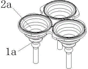
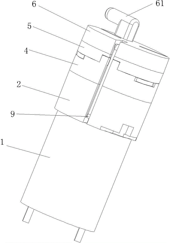
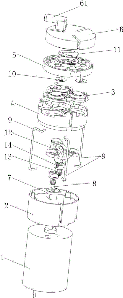
[0040] Figure 1 to Figure 19As shown, a miniature vacuum pump includes a motor 1, a housing 2, an air bag 3 with three bell-shaped bodies 31, an air bag seat 4, a valve seat 5, an upper cover 6 with a suction pipe 61, and the motor 1 is fixed on the shell. The bottom surface of the body 2, the drive shaft of the motor 1 extends into the housing 2, a runner 7 is fixed on the drive shaft of the motor 1, and the lower end of a pendulum shaft 8 is inserted on the runner 7, and the axis of the pendulum shaft 8 is in line with that of the runner 7. The central axes intersect, and the airbag seat 4, the valve seat 5 and the upper cover 6 are sequentially connected along the upper part of the housing 2 and fixed to each other. A corresponding draw-in groove, the draw-in groove is equipped with jumper 9 and housing 2, air bag seat 4, valve s...


PUM


Abstract

The invention discloses a mini vacuum pump which comprises a motor, a casing, an air sac provided with at least one bell-shaped body, an air sac seat, a valve seat and an upper cover provided with an air suction tube. The air sac comprises a partition board connected to the upper ends of the at least one bell-shaped body, and middle portions of bell-shaped bodies protrude upwards towards the partition board direction. First ring seal protrusions matched with the lower end surface of the valve seat are arranged around the bell-shaped bodies on the upper end surface of the partition board, and cavities are arranged on the lower end surface of the valve seat corresponding to the bell-shaped bodies. The cavities are sealed by the first ring seal protrusions, and suction channels and exhaust channels are arranged in the cavities. First air outlets are arranged on the upper end surface of the valve seat, second air outlets are arranged in the partition board, third air outlets are arranged on the upper end surface of the air sac seat, and an air outlet channel is arranged in the casing. The suction channels on the cavities are communicated with the air suction tube of the upper cover through a first air passing channel in the valve seat, and the first air outlets in the valve seat are communicated with the exhaust channels in the cavities through a second air passing channel in the valve seat. The mini vacuum pump is low in operation noise, high in vacuum degree and low in energy consumption.

Description

technical field [0001] The invention relates to a vacuum pump, in particular to a miniature vacuum pump. Background technique [0002] On August 19, 2009, an invention patent with the patent number ZL200820167649.2 and the name "Miniature Vacuum Pump" was published, which includes the front cover, the ventilation seat, the umbrella-shaped air valve, the stator, the air drum fixing seat, the air drum, Rear end cover, DC motor, the DC motor is connected with the rear end cover, the output shaft of the DC motor is connected to the eccentric wheel, and a swing rod bracket is arranged between the eccentric wheel and the stator. The spherical surfaces are connected to the stator, the swing rod bracket is fixed on the swing rod, the swing rod bracket is connected to the lower part of the air drum, and the end of the front end cover is provided with an air suction pipe and an exhaust pipe. From its disclosed accompanying drawing, the bottom of the air drum it adopts is bell-shaped,...

Claims


Application Information

Patent Timeline
Patent Type & Authority Patents(China)
IPC IPC(8): F04B37/14F04B45/00
Inventor 颜宏
Owner XIAMEN CONJOIN ELECTRONICS TECH
Why Eureka
Try Eureka