Cycle valve

A technology for valves and valve stems, applied in the field of valves, which can solve the problems of reducing valve maintenance and not having rubber valve cores, and achieves the effects of long-term use, reduced maintenance, and reduced trouble

Inactive Publication Date: 2013-02-13
CHANGZHOU XINXI HUAYA TOOLS
View PDF2 Cites 0 Cited by
  • Summary
  • Abstract
  • Description
  • Claims
  • Application Information

AI Technical Summary

Problems solved by technology

[0003] Aiming at the defects of the existing valves, the present invention designs a valve without a rubber valve core, which overcomes the air leakage problem caused by the aging of the valve core, reduces people's maintenance on the valve, and is beneficial to the maintenance of the valve. long time use

Method used


Image

  • Cycle valve
  • Cycle valve

Examples


Embodiment Construction

[0013] The present invention will be further elaborated below in conjunction with accompanying drawing:

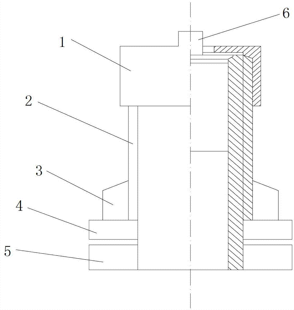
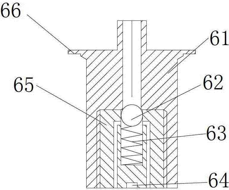
[0014] Such as figure 1 and figure 2 The shown valve includes a hollow valve stem 2, the lower end of the valve stem 2 is provided with an upper pressing piece 4 and a lower pressing piece 5 connected to the tire body, and the upper pressing piece 4 and the lower pressing piece 5 are respectively arranged on the tire The upper surface and the lower surface of the upper surface and the lower surface form a clamping. The outer surface of the valve stem 2 is provided with threads, and the valve stem 2 is also provided with a positioning nut 3 for positioning the valve stem 2. The positioning nut 3 is used to connect the valve stem 2 with the valve stem 2. The steel rings are locked, and a valve core 6 is arranged inside the valve stem 2, and a valve locking cover 1 is also connected to the top of the valve stem 2, and the valve core 6 includes an outer core body 61 and an i...


PUM


Abstract

The invention belongs to the field of bicycle parts, and especially relates to a novel cycle valve. The cycle valve comprises a hollow valve rod; an upper pressing sheet and a lower pressing sheet which are connected with a tire body are arranged at the lower end of the valve rod; threads are arranged on the outer surface of the valve rod; a positioning nut which is used for positioning the valve rod is further arranged on the valve rod; a valve core is arranged in the valve rod; the top of the valve rod is connected with a valve locking cover; the valve core comprises an outer core body and an inner core body; a through hole for the flowing of air is arranged in the outer core body; the outer core body at the lower end of the through hole is provided with a cavity; the inner core body is arranged in the cavity of the outer core body; the inner core body is provided with a blind hole at a place corresponding to the through hole; the diameter of the blind hole is greater than the diameter of the through hole; a sealing ball and a spring which is used for resetting the sealing ball are arranged in the blind hole; and air flow channels which are communicated with a tire cavity are arranged on two sides of the blind hole. Through the cycle valve, the air leakage problem caused by the ageing of the valve cores is overcome and the maintenance of the cycle valves is decreased.

Description

technical field [0001] The invention belongs to the field of bicycle parts, in particular to a novel air valve. Background technique [0002] In existing non-motor vehicle tires, all valves are equipped with valve needles, valve cores and valve compression nuts. When inflating, compressed air passes through the small holes of valve needles and enters the tire, and the valve cores play a role in sealing. When using a non-motorized vehicle, the valve core (rubber hose) is squeezed, rubbed and the temperature inside the tire changes, and the valve core ages faster, causing the tire to leak easily and affecting the user's health. Therefore, the present invention improves the valve for the deficiencies in the prior art. Contents of the invention [0003] Aiming at the defects of the existing valves, the present invention designs a valve without a rubber valve core, which overcomes the air leakage problem caused by the aging of the valve core, reduces people's maintenance on th...

Claims


Application Information

Patent Timeline
Patent Type & Authority Applications(China)
IPC IPC(8): F16K15/20F16K15/04
Inventor 蒋定专
Owner CHANGZHOU XINXI HUAYA TOOLS
Why Eureka
Try Eureka