Measuring the damage to a turbine-blade thermal barrier

A technology of heat insulation layer and lining layer, which is applied in the direction of supporting elements, measuring devices, and material defect testing of blades, and can solve problems such as the inability to predict the remaining life of components

Active Publication Date: 2013-02-13
SN DETUDE & DE CONSTR DE MOTEURS DAVIATION S N E C M A
View PDF12 Cites 2 Cited by
  • Summary
  • Abstract
  • Description
  • Claims
  • Application Information

AI Technical Summary

Problems solved by technology

[0006] Existing methods, which only work by detecting a defect, cannot predict the remaining life of a component or intervene before damage becomes severe

Method used


Image

  • Measuring the damage to a turbine-blade thermal barrier
  • Measuring the damage to a turbine-blade thermal barrier
  • Measuring the damage to a turbine-blade thermal barrier

Examples


Embodiment Construction

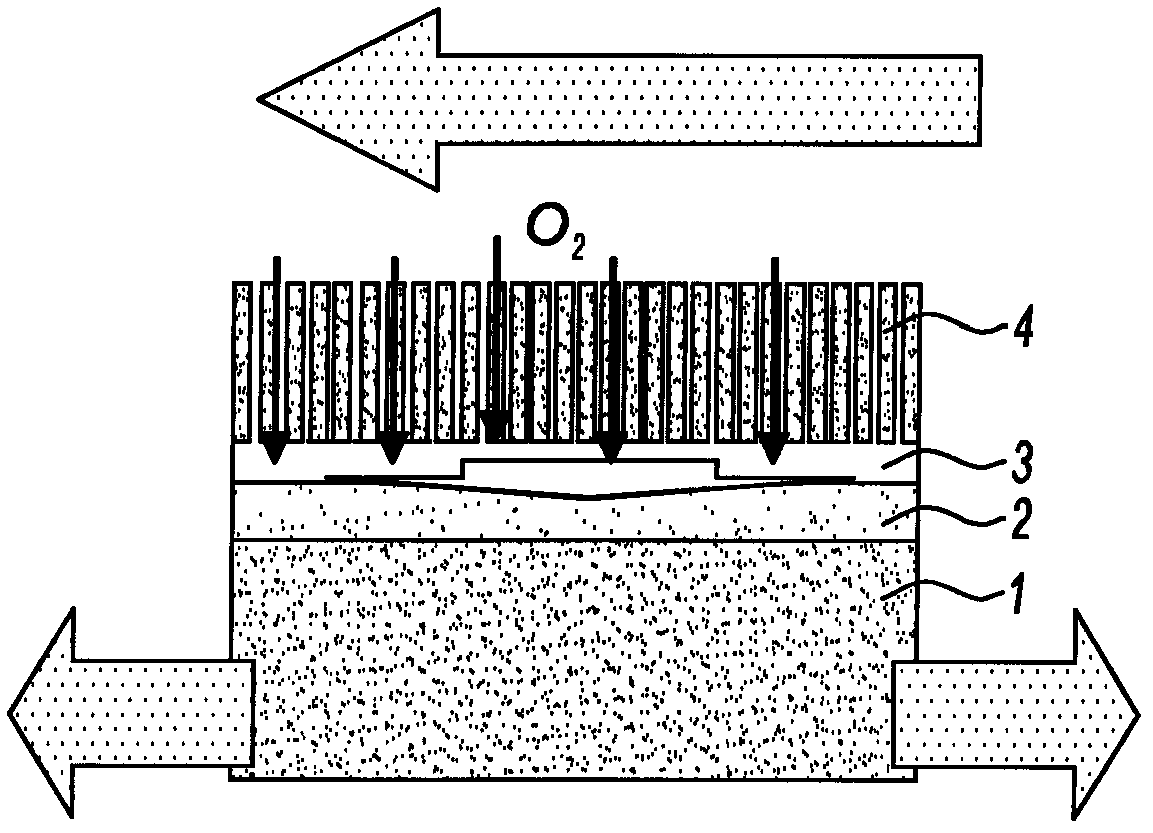
[0029] refer to figure 1 , a cross-sectional view of the composition of an insulating layer disposed on the surface of a turbine blade can be seen. The metallic composition of the blade, typically a superalloy containing nickel, forms a substrate 1 on which is deposited an aluminum layer 2 sandwiched between the substrate 1 and the ceramic layer 4 . The role of this aluminum layer is to give the assembly a certain elasticity so that it can absorb the difference in thermal expansion that exists between the substrate 1 with high thermal expansion and the ceramic 4 with low thermal expansion.

[0030] The ceramic 4 has a columnar structure, which allows lateral displacement due to the appearance of cracks between the columns. However, one consequence of this is that the aluminum comes into contact with oxygen brought in by the gases flowing in the jets of the turbine engine. The aluminum layer 2 is then converted to an aluminum oxide layer 3 at a certain thickness. The thickne...


PUM


Abstract

Method for evaluating the damage to a thermal barrier applied to a component made from a metal substrate, said thermal barrier comprising a sublayer of aluminium and a layer of columnar-structure ceramic material, said sub-layer being positioned between said substrate and said ceramic layer, characterized in that it comprises a first step of calibration comprising the selection of a determined number of calibration components that have undergone various degrees of damage, exposing them for a given length of time to radiation, measuring the temperature obtained at the surface after the given length of time and establishing a curve connecting an increase in temperature to damage, and a second step of measuring the damage to the thermal barrier of said component that involves exposure to said radiation for said length of time, measuring the temperature obtained, and relating the increase in temperature to the calibration curve in order, from said curve, to extract the level of damage.

Description

technical field [0001] The present invention relates to the field of turbine engines and, more particularly, to the field of the life of the components of these turbine engines subjected to high temperatures. Background technique [0002] Components of the hot part of a turbine engine, in particular the turbine blades, are subjected to extremely high temperature conditions in use and protective measures have been envisaged to subject them to these extreme conditions. Among these measures are the deposition of coatings, called thermal barriers, on their outer surfaces which protect the metal in which they are formed. The thermal barrier typically consists of a ceramic layer of approximately 100 microns deposited vertically onto the surface of the metal layer. An aluminum liner of tens of microns is placed between the ceramic and the metal base, completing the thermal barrier by providing a bond between these two components together with oxidation protection of the blade meta...

Claims


Application Information

Patent Timeline
Patent Type & Authority Applications(China)
IPC IPC(8): F01D5/28G01N25/72
CPCG01N25/72G01N17/006F01D5/288
Inventor 昆廷·米斯托拉
Owner SN DETUDE & DE CONSTR DE MOTEURS DAVIATION S N E C M A
Why Eureka
Try Eureka