Zip and zip teeth thereof

A zipper and sprocket technology, applied in the field of zippers and their sprockets, can solve the problems of limited lateral pulling force, water leakage of sprockets 101, lack of engaging structure, etc., so as to achieve the effect of improving meshing strength and increasing close effect.

Inactive Publication Date: 2013-02-20
冠宇拉炼股份有限公司
View PDF4 Cites 8 Cited by
  • Summary
  • Abstract
  • Description
  • Claims
  • Application Information

AI Technical Summary

Problems solved by technology

[0009] However, the structure of the fourth existing slide fastener 10 is the same as that of the second and third existing slide fasteners 8, 9, the sprocket 101 is divided into the surface portion 103 and the back portion 104, and the fourth existing slide fastener The first head 103b formed by the surface portion 103 of the slide fastener 9 also lacks the design of the engaging structure
Therefore, closing the existing zipper 10 only by means of the structural design of the mutual engagement of the back parts 104 also makes the fourth type of the existing zipper 10 able to withstand a relatively limited lateral pulling force, and the force is relatively poor and unstable. , resulting in the fourth existing zipper 10 still having the disadvantage of poor engagement strength
[0010] Furthermore, please refer to Figure 7 As shown, there is still a gap (G) when each of the surface parts 103 and each of the back parts 104 are engaged respectively, and the gap (G) of each of the surface parts 103 and the gap (G) of each of the back parts 104 communicate with each other, In this way, the liquid can directly infiltrate into the interior through the gaps (G) of each of the surface parts 103 through the gaps (G) of each of the back parts 104, so the sprockets 101 of the fourth type of existing slide fastener 10 still exist. water leak concerns
Also, although the fourth type of existing zipper 10 can repel water by applying a water-repellent agent to each of the sprockets 101, it is still easy to cause water repellency to deteriorate after repeated washing and long-term use.

Method used


Image

  • Zip and zip teeth thereof
  • Zip and zip teeth thereof
  • Zip and zip teeth thereof

Examples


Embodiment Construction

[0067] In order to make the above and other objects, features and advantages of the present invention more obvious and understandable, the following is a detailed description of the preferred embodiments of the present invention in conjunction with the accompanying drawings:

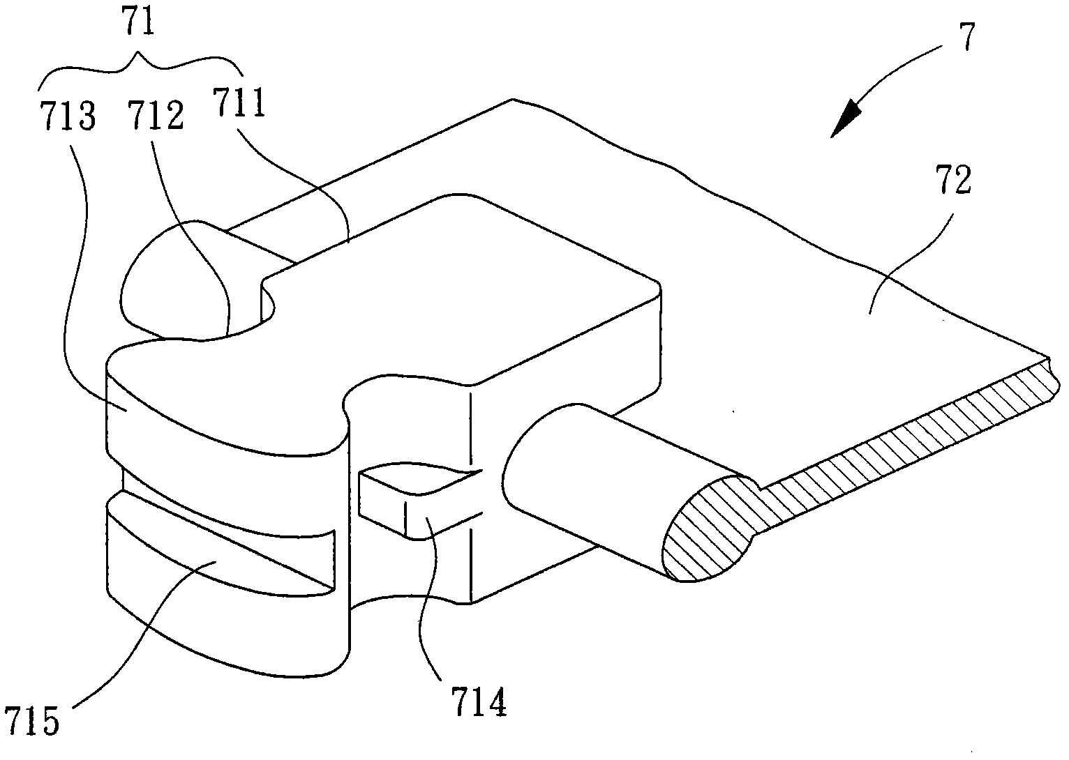
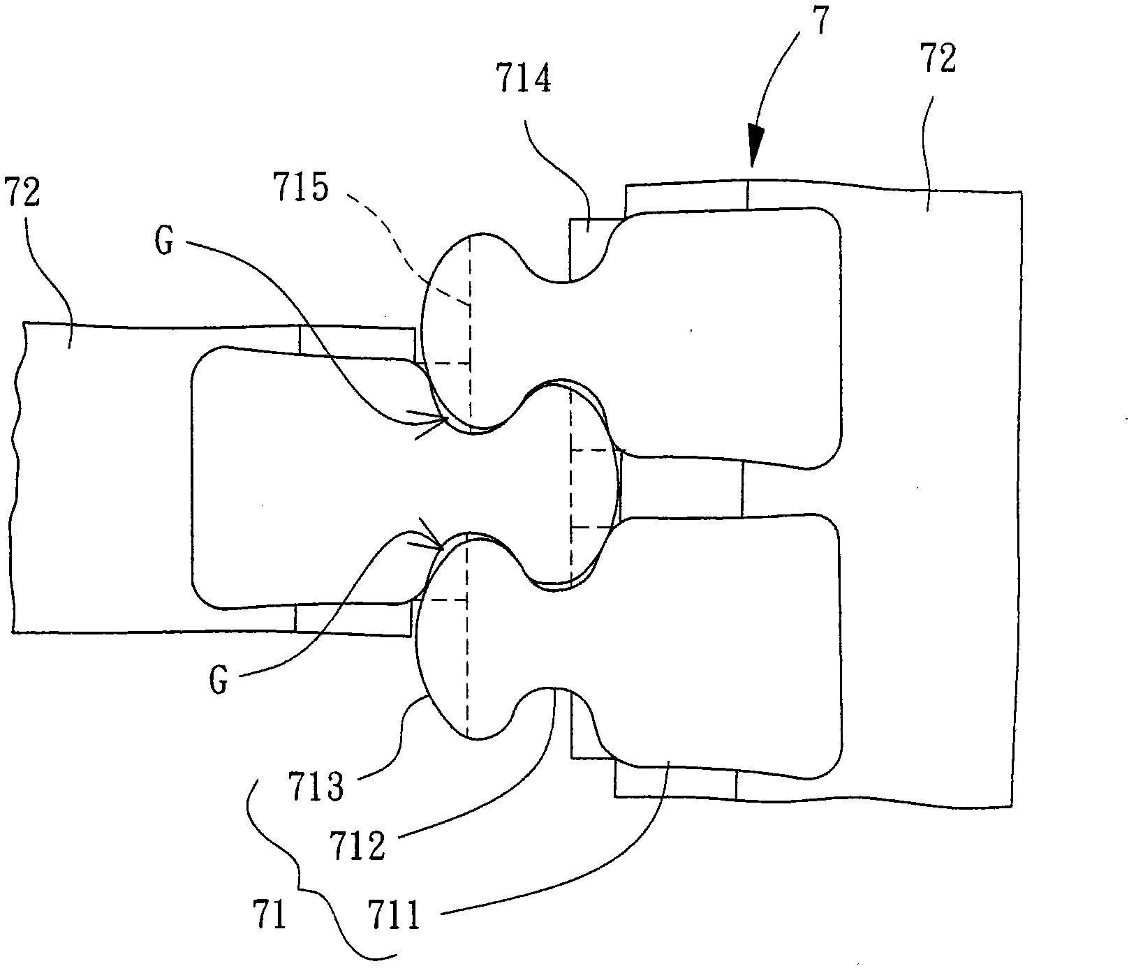
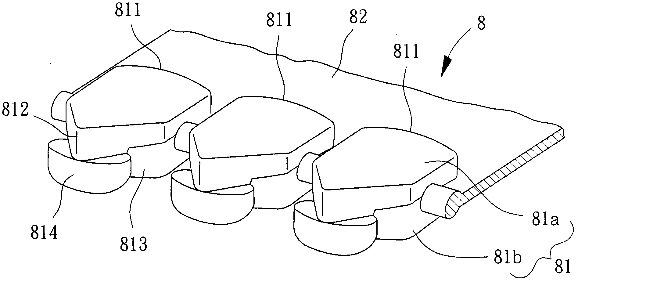
[0068] Please refer to Figure 8 to Figure 10 As shown, the zipper in the preferred embodiment of the present invention can be applied to various types of clothing such as jackets, trousers or raincoats, and can also be applied to structures such as clothing pockets, backpacks or waterproof bags. The zipper is composed of two chain cloths 1 and a plurality of chain teeth 2, the two chain cloths 1 are arranged oppositely, and the several chain teeth 2 are arranged in a staggered arrangement on the side edges of the two chain cloths 1 opposite to each other; Picture 9 As shown, it is a schematic diagram showing that a chain cloth 1 is provided with several chain teeth 2 side by side. In addition, each of the ...


PUM


Abstract

The invention relates to a zip. The zip comprises two zip cloth and a plurality of zip teeth, wherein each zip cloth comprises a yarn core, the plurality of zip teeth are arranged on the two yarn cores, each of the zip teeth is provided with a first meshing member and a second meshing member, the first meshing members are arranged on the zip cloth through first supporting portions and are provided with first locking portions, auxiliary locking portions are arranged between the first locking portions and the first supporting portions, a first clamping groove and an auxiliary clamping groove are formed between two adjacent first meshing members, the first clamping grooves and the auxiliary clamping grooves are respectively used for meshing the first meshing portions with the auxiliary locking portions, the zip cloth is clamped by the second meshing members and the first meshing members through second supporting members, each of the second meshing members is provided with a second clamping portion, a second clamping groove is formed between two adjacent second meshing members, and the second clamping grooves are used for meshing the second clamping portions. By the aid of the opposite relation of detail structures of the first meshing members and the second meshing members, the sealing effect and the meshing strength are improved.

Description

Technical field [0001] The invention relates to a zipper and its elements, in particular to a zipper and its elements with good adhesion. Background technique [0002] Please refer to figure 1 and figure 2 Shown here is the invention patent of "Sliding fastener chain" of Taiwan Patent Publication No. I317266, which discloses the first existing zipper 7, which is composed of several chain teeth 71 and two chain cloth 72. The chain The teeth 71 are arranged on the opposite side edges of the two chain cloths 72, and the chain teeth 71 of each chain cloth 72 are misaligned. For the convenience of description, only one of the chain teeth 71 and one of the chain cloths 72 is used for description below. The sprocket 71 belongs to a single-tooth structure, and the sprocket 71 is formed on the side edge of the chain cloth 72 by a supporting portion 711; the sprocket 71 forms a neck 712 with a reduced diameter in the middle part, and the neck 712 An enlarged engaging head 713 is connect...

Claims


Application Information

Patent Timeline
Patent Type & Authority Applications(China)
IPC IPC(8): A44B19/24A44B19/06
Inventor 郑荣元
Owner 冠宇拉炼股份有限公司
Why Eureka
Try Eureka