Narrow lifting chain traversing conveyor

A technology of lifting chains and conveyors, applied in the field of conveyors, can solve the problems of reducing the transmission power of roller conveyors and unfavorable material transportation

Inactive Publication Date: 2013-02-20
WUXI MINGZHU TURBOCHARGER MFG
View PDF4 Cites 4 Cited by
  • Summary
  • Abstract
  • Description
  • Claims
  • Application Information

AI Technical Summary

Problems solved by technology

[0002] On the roller conveyor, the objects need to be transported horizontally during the transportation of the objects. The existing horizontal transportation equipment for the objects uses a chain traverse conveyor. The existing chain traverse conveyor is shown in figure 1 , the drive sprocket 1 drives the end sprockets 3-1 and 3-2 on both sides of the drive sprocket through the chain 2, and the chain 2 circulates to realize the transportation of materials on the chain 2. In this structure, when the chain moves laterally When the conveyor is set in the roller conveyor, the chain and the sprocket in the chain traverse conveyor must protrude from the gap between the rollers in the roller conveyor to realize material transportation. In order to ensure that the chain and the sprocket protrude, the roller The gap requires a large design, which reduces the transmission power of the roller conveyor, and also causes the material to be stuck in the gap between the rollers, which is not conducive to the transportation of the material (4 in the figure is the supporting wheel)

Method used


Image

  • Narrow lifting chain traversing conveyor
  • Narrow lifting chain traversing conveyor
  • Narrow lifting chain traversing conveyor

Examples


Embodiment Construction

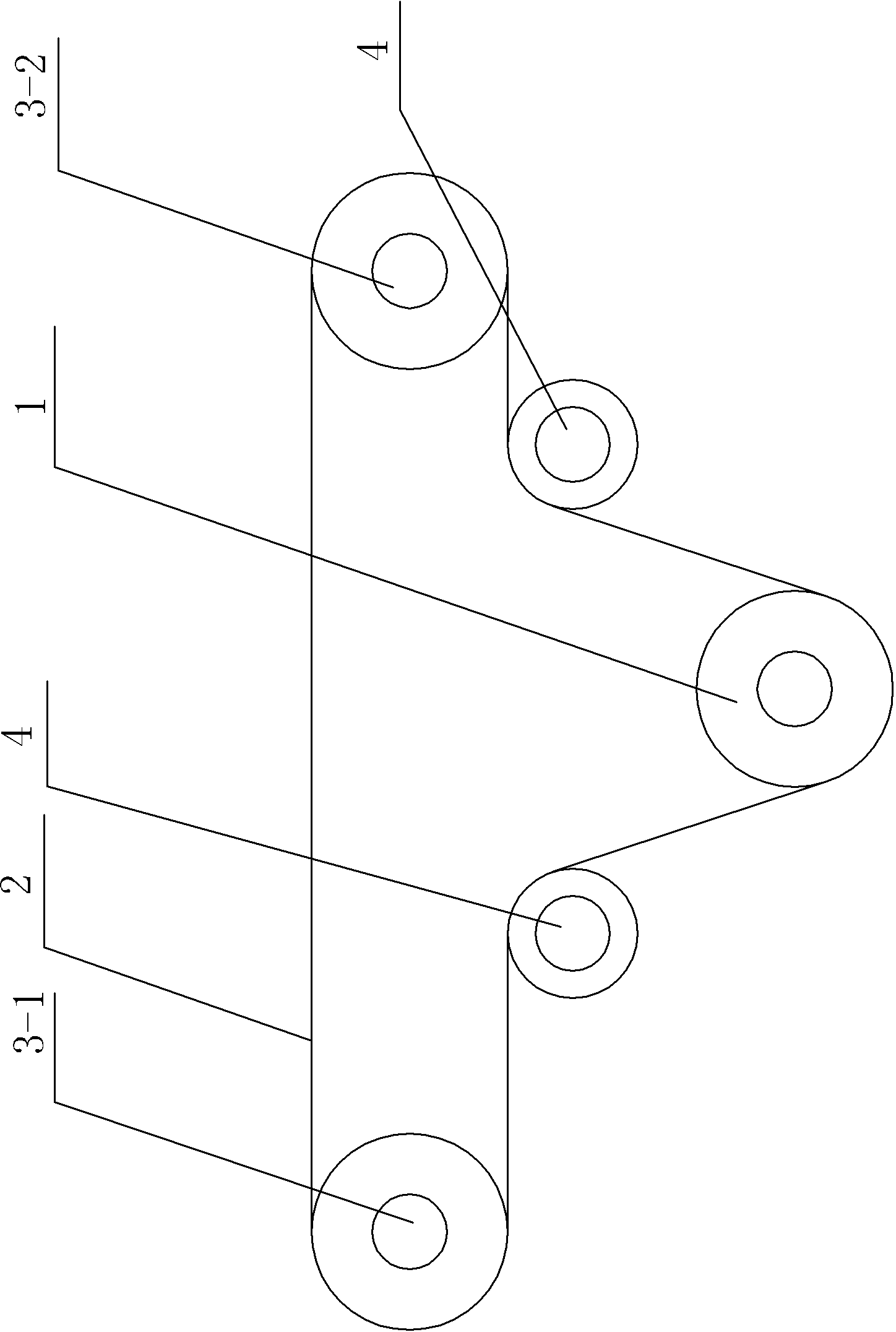
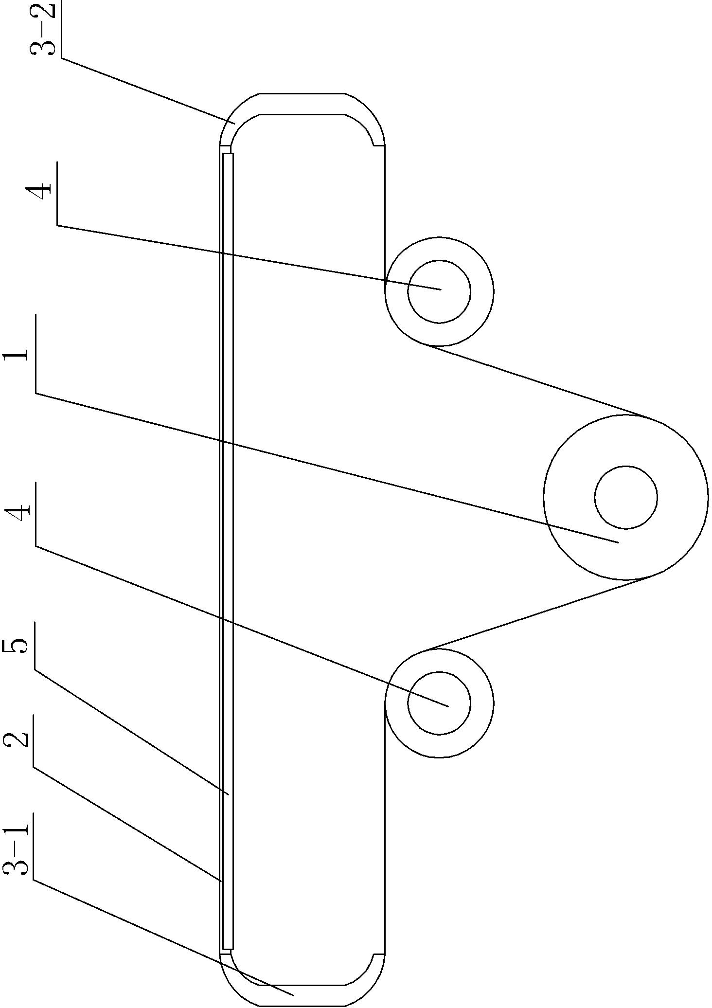
[0012] See figure 2 , a narrow lifting chain traverse conveyor, which includes a driving sprocket 1 and a chain 2, the two ends of the driving sprocket 1 are provided with nylon guide strips 3-1, 3-2, and the chain 2 passes through the driving sprocket 1 and the two ends Nylon guide strips 3-1, 3-2 form a closed loop. A supporting guide bar 5 corresponding to the chain 2 is arranged between the nylon guide bars 3-1, 3-2, and a supporting wheel 4 is respectively arranged between the drive sprocket 1 and the nylon guide bars 3-1, 3-2 at both ends, The supporting roller 4 supports the chain between the drive sprocket 1 and the nylon guide bar, so that the chain remains in tension.

[0013] Combine below figure 1 , figure 2 , image 3 , Figure 4 , Figure 5 To illustrate the working principle of the narrow lifting chain traverse conveyor of the present invention:

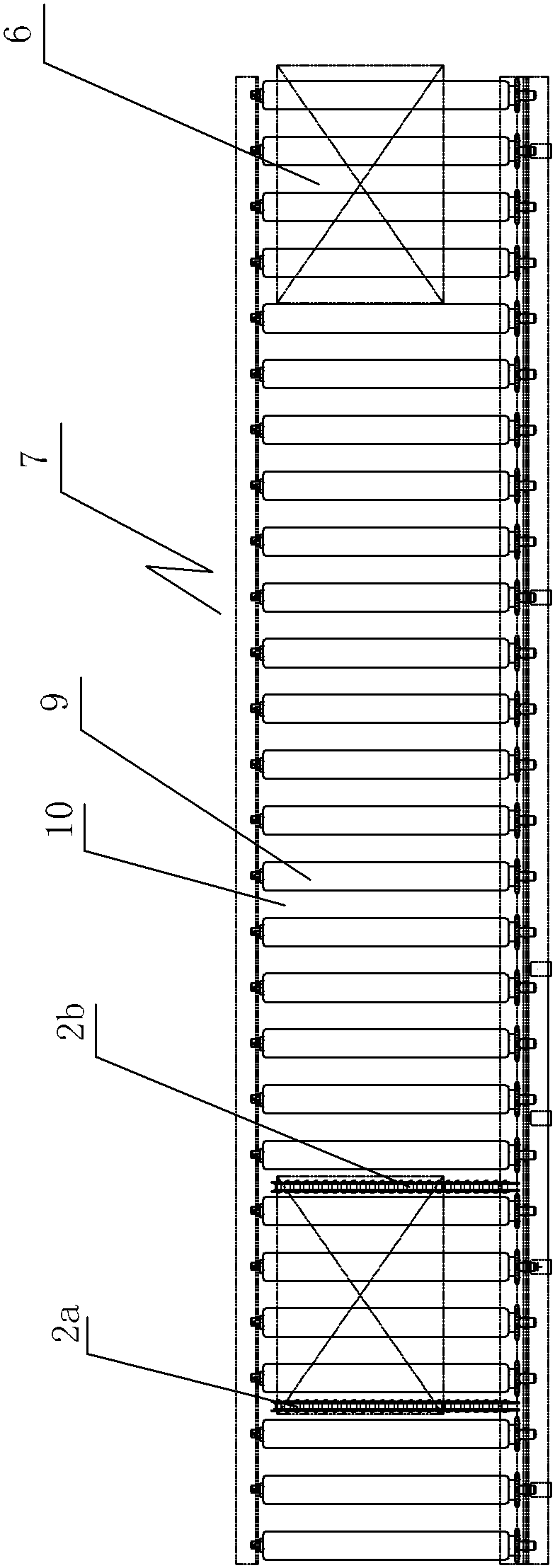
[0014] When the material 6 is transported to the position of the narrow lift chain traverse conveyor throug...


PUM


Abstract

The invention provides a narrow lifting chain traversing conveyor capable of reducing a gap formed between rolling wheels so as to increase the transmission power of a roller way conveyor, effectively prevent materials from being clamped into the gap formed between the rolling wheels and be convenient for the transportation of the materials. The narrow lifting chain traversing conveyor comprises a drive sprocket and a chain. The narrow lifting chain traversing conveyor is characterized in that both ends of the drive sprocket are provided with guide bars; and the chain and the guide bars positioned on both ends of the drive sprocket form a closed cycle through the drive sprocket.

Description

technical field [0001] The invention relates to the technical field of conveyors, in particular to a narrow lift chain traverse conveyor. Background technique [0002] On the roller conveyor, the objects need to be transported horizontally during the transportation of the objects. The existing horizontal transportation equipment for the objects uses a chain traverse conveyor. The existing chain traverse conveyor is shown in figure 1 , the drive sprocket 1 drives the end sprockets 3-1 and 3-2 on both sides of the drive sprocket through the chain 2, and the chain 2 circulates to realize the transportation of materials on the chain 2. In this structure, when the chain moves laterally When the conveyor is set in the roller conveyor, the chain and the sprocket in the chain traverse conveyor must protrude from the gap between the rollers in the roller conveyor to realize material transportation. In order to ensure that the chain and the sprocket protrude, the roller The gap requi...

Claims


Application Information

Patent Timeline
IPC IPC(8): B65G47/54
Inventor 高锡民
Owner WUXI MINGZHU TURBOCHARGER MFG
Why Eureka
Try Eureka