
Method and device for identifying network topological map

A technology of a network topology map and a recognition device, which is applied in the field of image recognition, can solve the problems that the topology map cannot be used directly, is not suitable for network topology map recognition, etc., and achieves the effect of improving efficiency

Active Publication Date: 2013-02-20
连邦网络科技服务南通有限公司
View PDF3 Cites 3 Cited by
  • Summary
  • Abstract
  • Description
  • Claims
  • Application Information

AI Technical Summary

Problems solved by technology

However, the network topology diagrams used in current communication network design and planning are usually pictures completed by drawing tools (such as Auto-CAD). Network design and planners can obtain electronic or printed pictures generated by drawing tools or even hand-drawn topologies These topology diagrams cannot be directly used in the subsequent IP RAN network planning and design. As a result, network design and planners can only manually work on the diagram in the network design and planning software based on the above topology diagrams, and then continue to IP in the network design and planning software. Design of RAN network planning
[0003] Existing image recognition technologies such as word processing, formula processing, face fingerprint recognition, etc., usually abstract the main features of the image before identification, and then identify the same or similar images in the existing feature data. However, the above-mentioned image recognition technology is not suitable for the recognition of network topology diagrams. For example, the device types of network elements in the topology diagram need to be defined by users, and the images and colors representing network elements are defined by users according to their preferences, which has great randomness. This makes it impossible to extract the main features of the image from the network topology map for recognition

Method used


Image

  • Method and device for identifying network topological map
  • Method and device for identifying network topological map
  • Method and device for identifying network topological map

Examples


Embodiment Construction

[0022] The following will clearly and completely describe the technical solutions in the embodiments of the present invention with reference to the accompanying drawings in the embodiments of the present invention. Obviously, the described embodiments are only some, not all, embodiments of the present invention. Based on the embodiments of the present invention, all other embodiments obtained by persons of ordinary skill in the art without creative efforts fall within the protection scope of the present invention.

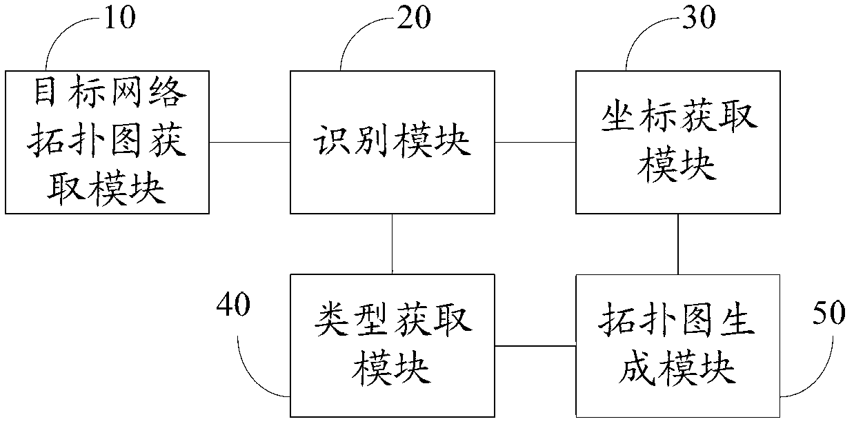
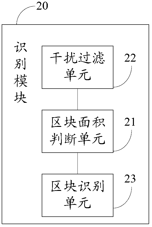
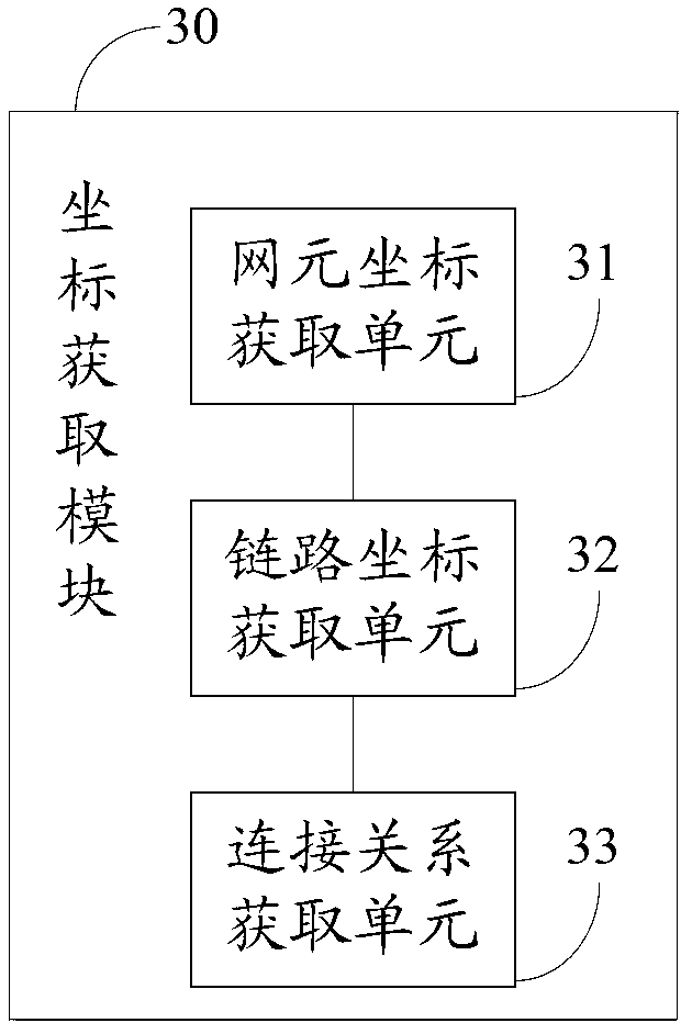
[0023] figure 1 It is a schematic structural diagram of an identification device for a network topology diagram in an embodiment of the present invention. As shown in the figure, the identification device for a network topology diagram in this embodiment at least includes a target network topology diagram acquisition module 10, an identification module 20, and a coordinate acquisition module 30 and the type acquisition module 40, wherein:

[0024] The target netwo...


PUM


Abstract

The embodiment of the invention discloses a method for identifying a network topological map. The method comprises the steps that: a target network topological map including pixel blocks of multiple colors is acquired; the pixel blocks of multiple colors are identified according to colors to obtain pixel blocks representing the network element, the link and the background in the target network topological map; the network element coordinate in the target network topological map and the connection relation between the link and the network element are acquired according to the coordinate of the pixel block in the target network topological map; and the type of the network element and the type of the link are acquired. The embodiment of the invention further discloses a device for identifying a network topological map. With the method and the device, key information in the network topological map can be simply analyzed instead of manually drawing a map by a network design planners, and therefore the efficiency of network design planning is greatly improved.

Description

technical field [0001] The invention relates to the field of image recognition, in particular to a method and device for recognizing a network topology map. Background technique [0002] The network deployment of IP RAN (Internet Protocol radio access network IP, wireless access network IP?) is usually large (hundreds to thousands of units), which leads to a heavy workload of network design and planning, and the best way to improve network design efficiency What is needed is to have a clear and intuitive network topology map. However, the network topology diagrams used in current communication network design and planning are usually pictures completed by drawing tools (such as Auto-CAD). Network design and planners can obtain electronic or printed pictures generated by drawing tools or even hand-drawn topologies These topology diagrams cannot be directly used in the subsequent IP RAN network planning and design. As a result, network design and planners can only manually wor...

Claims


Application Information

Patent Timeline
IPC IPC(8): H04L12/24G06K9/00
Inventor 安琦张南
Owner 连邦网络科技服务南通有限公司
Learn More