Blanking jig structure for plastic sheet

A plastic sheet punching technology, applied in the field of plastic sheet punching fixture structure, can solve the problem of low cutting efficiency and achieve high effect

Inactive Publication Date: 2013-02-27
WUXI NEST BIOTECHNOLOGY CO LTD
View PDF5 Cites 3 Cited by
  • Summary
  • Abstract
  • Description
  • Claims
  • Application Information

AI Technical Summary

Problems solved by technology

[0002] The specifications of the existing plastic sheet can be directly obtained through outsourcing, but for the size of the plastic sheet with special specifications, we need to cut it by hand, and the cutting efficiency is low

Method used


Image

  • Blanking jig structure for plastic sheet

Examples


Embodiment Construction

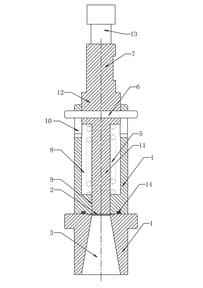
[0008] See figure 1 , which includes an upper mold and a bottom mold 1, a plastic sheet 2 is arranged in the middle of the punching position of the upper mold and the bottom mold 1, the bottom mold is provided with a lower mold cavity 3, and a plastic sheet 2 is arranged above the lower mold cavity 3, and the upper mold includes Sleeve 4, spring 5, pin 6, punch 7, the center of the sleeve 4 is provided with a punch installation hole, the punch installation hole is specifically divided into two sections: the upper section has a large aperture of 8, the lower section has a small aperture of 9, and the sleeve The upper ring surface of the barrel 4 is provided with a vertically arranged pin limit hole 10, the lower punch head 11 of the punch 7 passes through the punch installation hole and faces the plastic sheet 2 above the lower cavity 3, and the upper part of the punch 7 is supported The structure 12 is limited and connected in the pin limit hole 10 by the pin 6, the lower end ...


PUM


Abstract

The invention provides a blanking jig structure for a plastic sheet. A plastic sheet of a specific size can be obtained quickly, and the effect is good. The blanking jig structure comprises an upper die and a bottom die, wherein the plastic sheet is arranged between stamping positions of the upper die and the bottom die. The blanking jig structure is characterized in that the bottom die is provided with a lower die cavity; the plastic sheet is arranged above the lower die cavity; the upper die comprises a sleeve, a spring, a pin and a punch; a punch mounting hole is formed in the center of the sleeve and particularly divided into two sections; the upper section has a large diameter; the lower section has a small diameter; a pin limit hole is formed in a ring surface of the upper part of the sleeve; and a lower part punch of the punch penetrates through the punch mounting hole and then faces towards the plastic sheet above the lower die cavity.

Description

technical field [0001] The invention relates to the technical field of equipment structures for producing plastic sheet materials, in particular to the punching fixture structure for plastic sheet materials. Background technique [0002] The specifications of the existing plastic sheet can be obtained directly through outsourcing, but for the size of the plastic sheet with special specifications, we need to cut it by hand, and the cutting efficiency is low. Contents of the invention [0003] In view of the above problems, the present invention provides a punching tool structure for plastic sheets, which can quickly obtain plastic sheets of special specifications with high effect. [0004] Plastic sheet blanking jig structure, its technical scheme is as follows: it includes an upper mold and a bottom mold, and a plastic sheet is arranged in the middle of the stamping position of the upper mold and the bottom mold, and it is characterized in that: the bottom mold is provided...

Claims


Application Information

Patent Timeline
IPC IPC(8): B26F1/40B26F1/44
Inventor 许东良
Owner WUXI NEST BIOTECHNOLOGY CO LTD
Why Eureka
Try Eureka