Fixing structure for rotating material chamber in carbon extruder

A fixed structure and extruder technology, which is applied in the field of fixed structure of the rotating material chamber of the carbon extruder, can solve the problems such as loose fixing and easy loosening of the rotating material chamber, and achieve the effect of solving the problem of loose fixing and preventing vibration or rotation

Active Publication Date: 2014-11-05
TAIYUAN HEAVY IND
View PDF5 Cites 2 Cited by
  • Summary
  • Abstract
  • Description
  • Claims
  • Application Information

AI Technical Summary

Problems solved by technology

[0005] The purpose of the present invention is to solve the problems in the prior art that the rotating material chamber is not fixed firmly and is easy to loosen

Method used


Image

  • Fixing structure for rotating material chamber in carbon extruder
  • Fixing structure for rotating material chamber in carbon extruder

Examples


Embodiment Construction

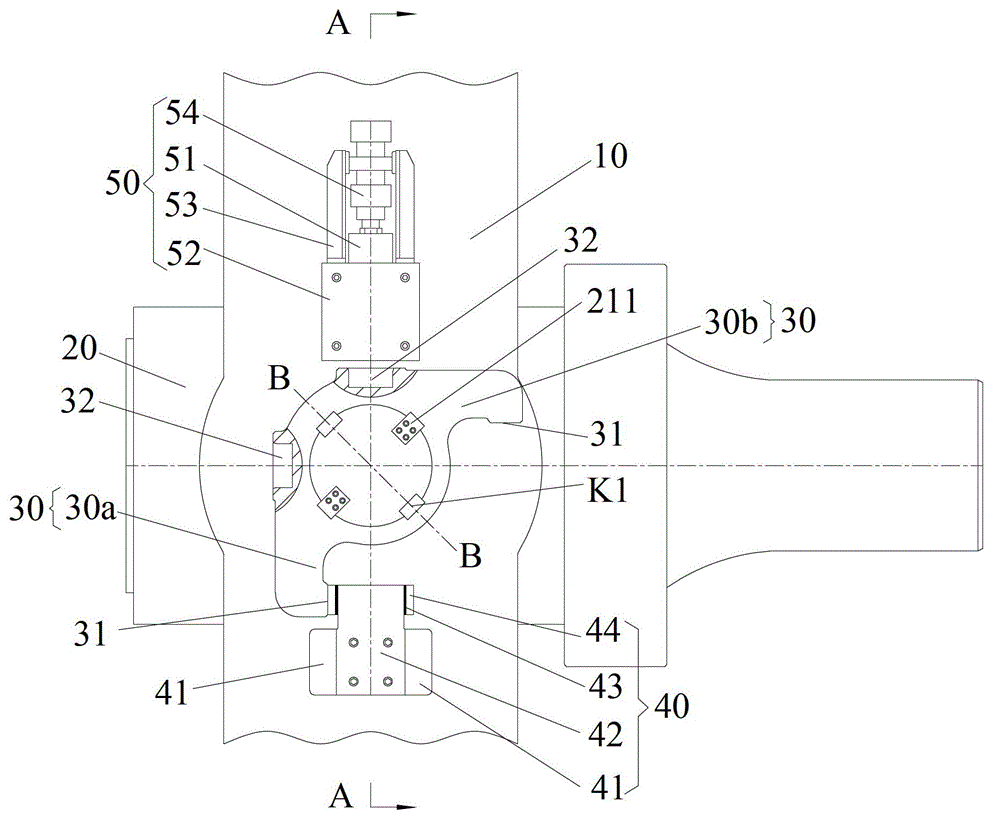
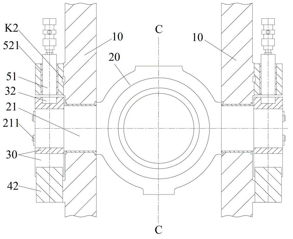
[0018] figure 1 It is a schematic diagram of an embodiment of the fixed structure of the rotary chamber of the carbon extruder of the present invention, figure 2 along figure 1 Sectional view of line A-A. Such as figure 1 and figure 2 As shown, in an embodiment of the present invention, the fixed structure of the rotating chamber of the carbon extruder is along the figure 2 The C-C line is left-right symmetrical, and includes two racks 10 , a rotating material chamber 20 , two rotating arms 30 , two positioning parts 40 and two latch parts 50 .

[0019] The rotating material chamber 20 is arranged between the two frames 10 and includes two symmetrically arranged trunnions 21 . Each of the two frames 10 has a shaft hole for the trunnion 21 to extend into, so that the rotating material chamber 20 can be rotatably arranged between the two frames 10 through the two trunnions 21, and the two trunnions 21 One end of each protrudes from the shaft holes of the two frames 10 r...


PUM


Abstract

The invention provides a fixing structure for a rotating material chamber in a carbon extruder. The fixing structure comprises two stands, the rotating material chamber, two rotating arms, two positioning parts and two bolt parts, wherein the rotating material chamber comprises two trunnions; the two trunnions respectively pass through shaft holes of the two stands to install the rotating material chamber between the two stands rotationally; the two rotating arms are respectively and fixedly mounted on the parts, extending out of the two stands, of the two trunnions; the rotating material chamber does not do relative movement with the two rotating arms; each positioning part and each bolt part are arranged on one side, adjacent to the corresponding rotating arm, of each stand; each rotating arm comprises two positioning surfaces and two grooves; and each bolt part comprises a bolt. The rotating material chamber can rotate to contact the two positioning surfaces with the two sides of each positioning part, and when one positioning surface is contacted with one positioning part, one bolt can be inserted into one groove to fix the corresponding rotating arm.

Description

technical field [0001] The invention relates to a fixed structure, in particular to a fixed structure for a rotary material chamber of a carbon extruder. Background technique [0002] The rotating material chamber is an important part of the vertical pounding horizontal extrusion carbon extrusion machine. When charging, the rotating material chamber is turned into a vertical state, and the carbon paste falls into the material chamber from the feeding chute, and then pre-pressed. After the pre-pressing is completed, the rotary material chamber is driven by the rotary drive cylinder to rotate from a vertical state to a horizontal state for extrusion, and the carbon paste is extruded from the nozzle to become a qualified extrusion product. [0003] In each cycle of carbon extrusion, the rotating material chamber must rotate twice, from horizontal to vertical, and then from vertical to horizontal. Requirements, and both the horizontal and vertical positions require the materia...

Claims


Application Information

Patent Timeline
Patent Type & Authority Patents(China)
IPC IPC(8): B28B3/20
Inventor 魏征宇薛峰
Owner TAIYUAN HEAVY IND
Why Eureka
Try Eureka